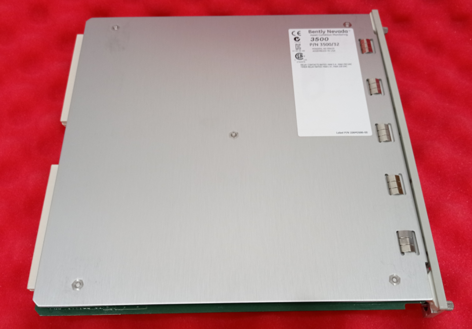
The 3500/32M 4-Channel Relay Module is a critical component of the 3500 Machinery Protection System. It is a full-height, key interface module that provides four independent relay outputs. Its core function is to translate the complex monitoring and alarm logic internal to the 3500 system (such as Danger, Alert, Channel Not-OK, and other statuses) into physical contact signals that can drive external equipment, thereby enabling critical safety functions like equipment shutdown, audible/visual alarms, and interlock control. Any number of 3500/32M modules can be installed in any of the slots to the right of the Transient Data Interface (TDI) module, providing users with a highly flexible and scalable relay output solution.
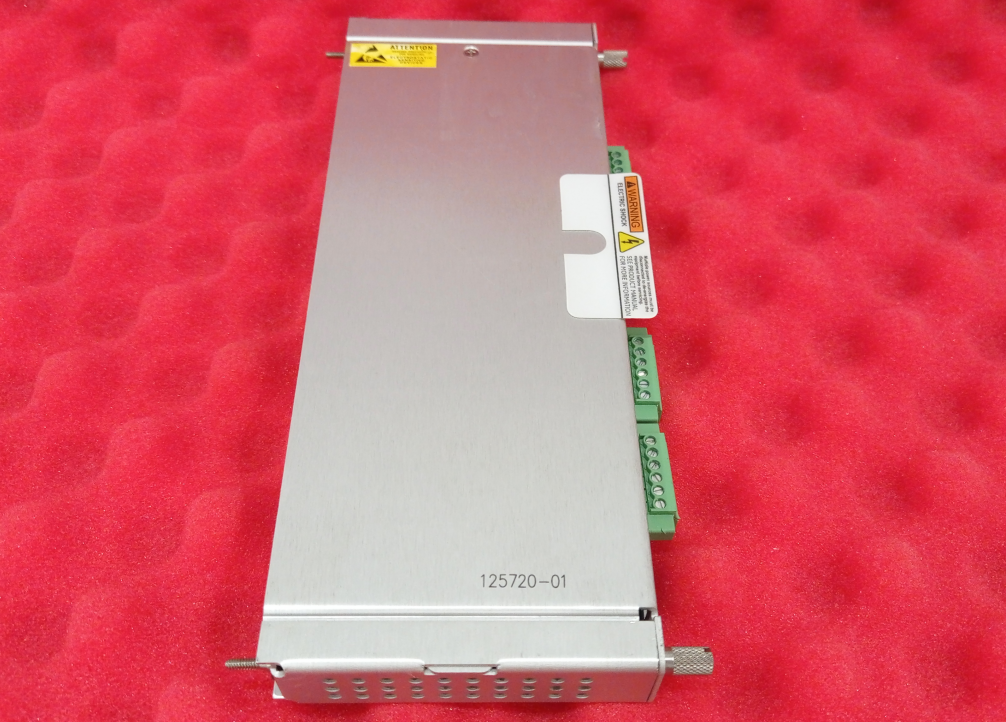
The 3500/32M consists of a fixed front card (149986-02) and a fixed rear card (125720-01). The module's excellence lies in the fact that each relay output is equipped with a highly configurable "Alarm Drive Logic." Using the 3500 Rack Configuration Software and AND/OR logic, users can freely combine alarm statuses (e.g., Danger, Alert), Channel Not-OK signals, or any Process Parameter Limit (PPL) points from any monitor channel within the rack to define the precise trigger conditions for each relay. This powerful flexibility allows it to meet various application needs, from simple single-alarm triggers to complex multi-parameter "voting logic," making it the ultimate execution unit for building reliable machine protection chains and process control logic.
Features
Independently Programmable Channels: The four relay channels are completely independent; each channel can be individually programmed to perform different logical functions and control different external devices.
Powerful Alarm Drive Logic (Voting Logic): This is the core function of the module. The operation of each relay is no longer limited to a single signal but can be controlled by multiple conditions combined through AND and OR logic.
Logic Input Sources: Can use the Danger and Alert alarm statuses, Channel Not-OK status, or any Process Parameter Limit (PPL) point from any monitoring channel as trigger conditions.
Application Example: Can implement redundant voting logic like "2oo3" (two-out-of-three), where a shutdown is only triggered if two out of three monitoring points alarm simultaneously, improving protection reliability while effectively preventing false shutdowns.
High-Performance Relays:
Type: Single-Pole, Double-Throw (SPDT), providing both Normally Open (NO) and Normally Closed (NC) contacts for flexible configuration.
Environmental Sealing: Epoxy-sealed, offering resistance to vibration, moisture, and dust, suitable for harsh industrial environments.
Arc Suppression: Standard built-in 250 Vrms arc suppressor protects contacts, reduces electrical spark interference, and extends lifespan.
Contact Life: Up to 100,000 operations (at 5 A, 24 Vdc, or 240 Vac).
Selectable Operation Mode: Each relay can be switch-selected on the module for Normally De-energized (NC contact active) or Normally Energized (NO contact active) mode, meeting the different fail-safe requirements of safety systems.
Comprehensive Status Indication: The module front panel features an independent CH ALARM LED indicator for each channel, which illuminates when that channel's relay is in an alarm state (contacts actuated), providing clear local status indication. It also includes OK LED (module operating normally) and TX/RX LED (module communicating with the rack) indicators.
Flexible Installation & Compatibility: Occupies one full-height front slot and one full-height rear slot (for the I/O module) in the 3500 rack. Can work with any version of 3500 monitor modules, seamlessly integrating into the entire 3500 system.
Extensive Certifications: The module has passed multiple international explosion-proof certifications such as cNRTLus (UL), ATEX, and IECEx (for Class I, Division 2 / Zone 2 areas), as well as safety and maritime certifications like CE, DNV GL, and ABS, meeting the installation and usage requirements for various harsh environments worldwide.
Working Principle & Technical Details
The working principle of the 3500/32M module is a process from "logical judgment" to "physical action."
Signal Input & Logical Processing:
The module continuously receives real-time status data from all monitor modules within the rack (e.g., 3500/42M Vibration Monitor, 3500/77M Pressure Monitor, etc.) via the 3500 rack's backplane bus. This data includes the alarm status (Alert/Danger), channel health (OK/Not-OK), and user-defined Process Parameter Limit (PPL) status for each channel.
Using the 3500 Rack Configuration Software, users define the unique "Alarm Drive Logic" for each relay channel of the 3500/32M. This logic is essentially a Boolean logic equation composed of AND and OR gates. For example, it can be programmed as: Relay 1 Activate = (Monitor1-ChannelA Danger) OR (Monitor2-ChannelB Alert AND Monitor3-ChannelC Not-OK).
The microprocessor inside the module continuously runs these configured logic equations, calculating in real-time whether each relay should be activated.
Relay Driving & Output:
When the logic equation calculation for a particular channel results in "true," the processor sends a signal to that channel's relay driver circuit.
The driver circuit, based on the mode switch position selected for that channel on the front panel (Normally Energized/Normally De-energized), decides whether to power the relay coil or not, thereby controlling the contact engagement or release.
Normally De-energized Mode: The relay coil is not energized in the non-alarm state. The Normally Closed (NC) contact is closed, and the Normally Open (NO) contact is open. Upon an alarm, the coil is energized, the NC contact opens, and the NO contact closes.
Normally Energized Mode: The relay coil is energized in the non-alarm state. The NO contact is closed, and the NC contact is open. Upon an alarm, the coil is de-energized, the NO contact opens, and the NC contact closes. This mode is often used for Fail-Safe design.
Contact Connection & Load Control:
The relay output contacts are brought out to terminal blocks via the rear I/O module. Users connect external circuits (e.g., shutdown solenoid valves, alarm horns, DCS input points, indicator lights) in series with the contact loop.
When the relay contacts change state due to the alarm logic trigger, they accordingly connect or disconnect the external circuit, thus executing the predetermined control or protection action.
Important Technical Details & Warnings:
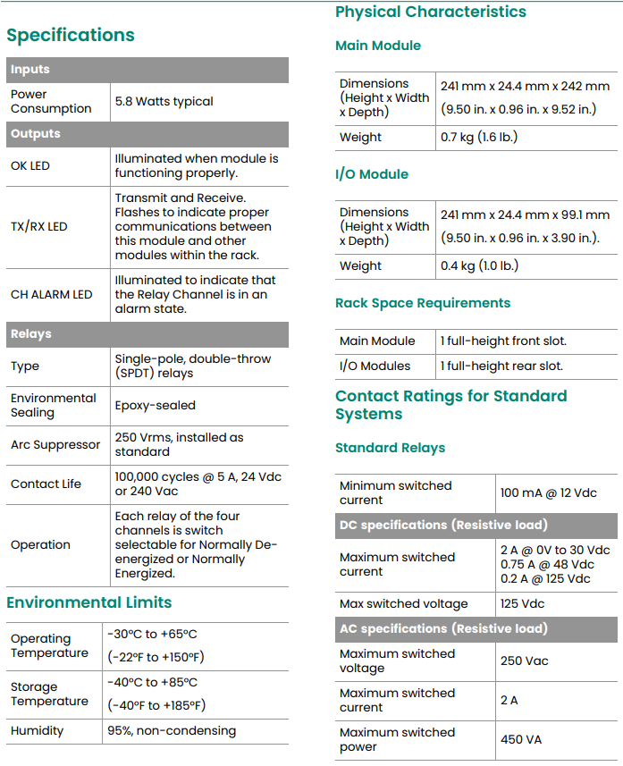
Standard System Contact Ratings: Can switch AC or DC loads.
DC (Direct Current): Maximum switched voltage 125 Vdc, maximum switched current 2A (at 0-30 Vdc).
AC (Alternating Current): Maximum switched voltage 250 Vac, maximum switched current 2A, maximum power 450 VA.
Functional Safety & Hazardous Area System Limitations: When the module is used in Functional Safety (SIL) systems or ordered with hazardous area approval options, the contact ratings are strictly limited to comply with the clearance and creepage distance requirements of the safety certifications.
Maximum DC Voltage: 30 Vdc
Maximum AC Voltage: 30 Vac
Maximum Current: 2A
The use of higher voltages in these applications is strictly prohibited, as it would violate the safety certificates and could create serious hazards.
Specifications
| Item | Specification Description |
| Number of Channels | 4 independent channels |
| Relay Type | Single-Pole, Double-Throw (SPDT), epoxy-sealed |
| Contact Life | 100,000 cycles (@ 5 A, 24 Vdc or 240 Vac) |
| Arc Suppression | Built-in, 250 Vrms |
| Operation Mode | Selectable per channel: Normally Energized or Normally De-energized |
| Standard Ratings | DC: 2A @ 30Vdc, 0.2A @ 125Vdc
AC: 2A @ 250Vac, 450 VA |
| Safety/Ex Ratings | DC/AC: 2A @ 30Vdc / 30Vac (Restricted Conditions) |
| Power Consumption | 5.8 Watts (typical) |
| Operating Temperature | -30°C to +65°C |
| Module Dimensions (HxWxD) | Main Module: 241 mm x 24.4 mm x 242 mm |
| Rack Space | 1 front slot (Main Module) + 1 rear slot (I/O Module) |
| Explosion-Proof Certification | cNRTLus (CL I, Div 2), ATEX/IECEx (II 3G Ex nA nC ic IIC T4 Gc) |
Application Scenarios
The 3500/32M 4-Channel Relay Module is an ideal choice for the following scenarios:
Critical Machine Shutdown Protection: This is its core application. When parameters like vibration, position, pressure, or temperature exceed dangerous limits, it triggers the relay to directly drive shutdown solenoid valves or cut off fuel sources, immediately stopping equipment operation to prevent catastrophic failure.
Redundant Voting Logic Systems: On critically monitored equipment with multiple probes (e.g., large compressors, steam turbines), it implements voting logic like "2oo3" (two-out-of-three), ensuring protection reliability while minimizing false shutdowns caused by a single probe failure.
Multi-Level Alarm Indication: Utilizes multiple relay channels to drive Alert and Danger indicator lights or audible/visual alarms separately, providing operators with clear, graded alarm information.
Signal Relaying & Isolation: Relays alarm signals from the 3500 system to Distributed Control Systems (DCS), Programmable Logic Controllers (PLC), or Fire & Gas (F&G) systems, while providing electrical isolation to protect the 3500 system from external interference.
Auxiliary Equipment Interlock Control: Controls the start/stop of auxiliary equipment like lube oil pumps, turning gear, and isolation valves based on the host machine's status.
Safety Instrumented System (SIS): Serves as the final element in an SIS (subject to strict rating limitations and safety procedures) to execute safety-critical functions.
Offshore Platforms & Ships: Widely used in the maritime sector, where high reliability and environmental adaptability are required, thanks to its maritime certifications.


