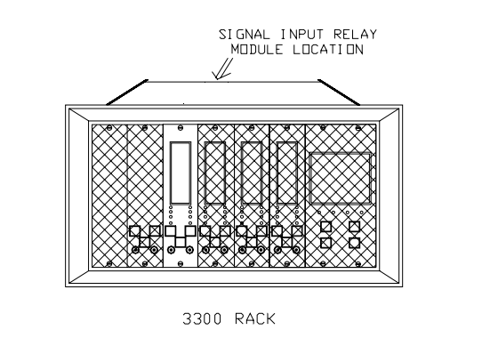
The 3300/16 XY/GAP Dual Vibration Monitor is a critical monitoring module within the Bently Nevada 3300 Series Asset Condition Monitoring system. It is a high-performance, highly configurable dedicated monitor primarily used for the continuous monitoring and protection of large rotating machinery, such as steam turbines, gas turbines, compressors, and pumps.
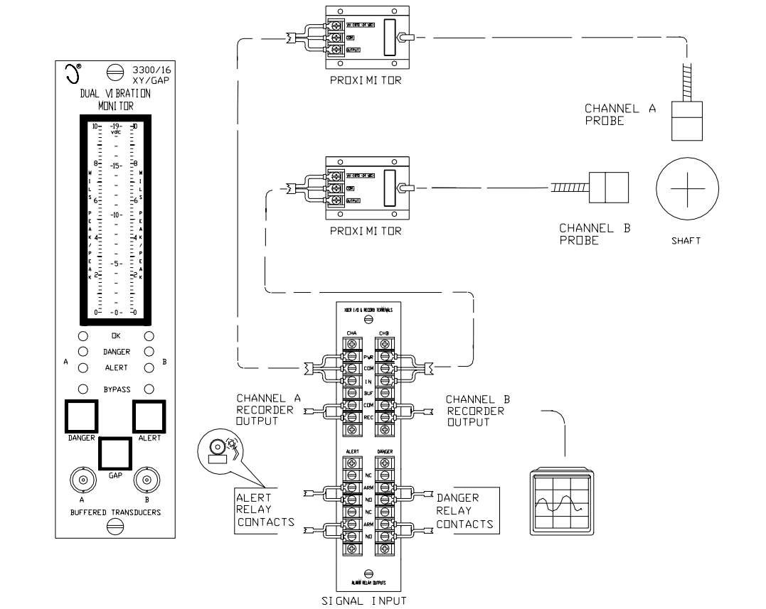
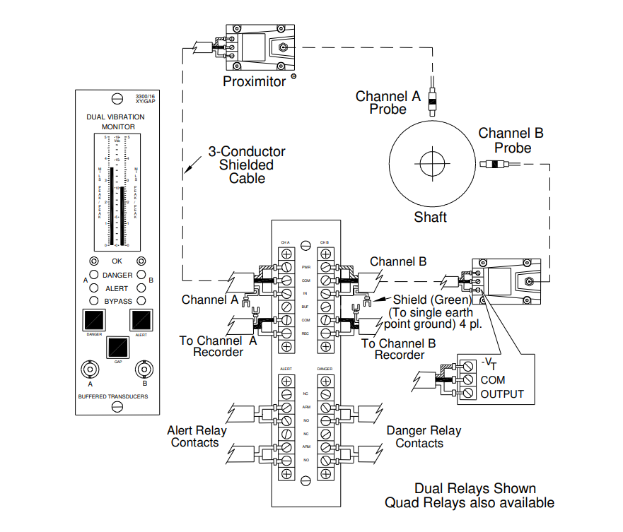
The monitor's core function is to simultaneously process two independent channels of radial vibration signals and additionally calculate and monitor a Gap signal representing the average shaft position. It accepts inputs from two proximity probe/Proximitor sensor systems, providing operators with a comprehensive view of the machine rotor's health. As an upgraded version of the 3300/15 Dual Radial Vibration Monitor, the key enhancement of the 3300/16 is the addition of radial position (Gap) alarms, offering more complete machine protection.
Its typical application involves installing two probes oriented 90 degrees apart (X and Y directions) on the same bearing. This configuration not only monitors the vibration amplitude in each direction but also, through the gap voltage, monitors the static position of the shaft (e.g., its lift within the bearing), which is crucial for detecting shaft misalignment, pre-load changes, or other mechanical issues.
2. System Functions and Monitoring Principles
2.1 Dual-Channel Vibration Monitoring
The 3300/16 monitor independently processes vibration signals for two channels. Each channel receives the raw voltage signal from a Proximitor sensor. This signal contains rich dynamic information about the rotor:
Dynamic AC Component: Represents the rotor's vibration. Its amplitude directly corresponds to the change in the gap between the rotor and the probe, typically expressed in peak-to-peak (pp) values.
Static DC Component: Represents the average gap between the probe tip and the shaft surface, reflecting the static position of the shaft.
The monitor's internal circuitry first separates the AC and DC components.
For vibration monitoring, the separated AC signal is filtered, amplified, and processed by a peak-to-peak detection circuit. This circuit calculates the voltage difference between the highest and lowest points of the vibration waveform, which directly corresponds to the vibration's peak-to-peak value. This processed signal is then compared against user-preset Alert and Danger alarm setpoints.
2.2 Gap Monitoring Principle
The "Gap" voltage, which is the separated DC component, is a core output of the eddy current proximity probe system. According to the eddy current principle, the average distance between the probe and the conductive shaft surface is inversely proportional to the output voltage (within the system's linear range). Therefore, a steady change in the gap voltage directly reflects an axial shift in the rotor's average position or a change in the bearing oil film thickness.
The 3300/16 monitor specifically provides a Gap Alarm function. Users can set an Alert alarm point for a specific gap voltage value. For instance, if the shaft position deviates from its optimal operating point due to factors like thrust bearing wear or temperature changes, the gap voltage will move outside the normal range and trigger an alarm, alerting the operator. This function adds an important layer of redundancy to machine protection. It is important to note that the gap alarm incorporates a fixed 6-second time delay to prevent nuisance trips caused by transient signal fluctuations.
2.3 Alarm Logic and Relay Outputs
The monitor provides two levels of alarm output for each channel:
Alert: A pre-warning level, indicating that vibration levels or gap values have entered a non-ideal range requiring attention.
Danger: A critical level, indicating the machine is in an unsafe operating condition, requiring immediate action to prevent damage.
The alarm relay module is an optional accessory, but at least one must be ordered per 3300 system. The relay mode is field-programmable:
Non-Latching: The relay automatically resets when the vibration level falls back below the alarm setpoint.
Latching: Once tripped, the relay remains in the tripped state until manually reset, which helps in identifying the first-out fault.
Furthermore, the Danger relay supports programmable Voting Logic:
"OR" Voting: The relay is driven if either channel trips a Danger alarm.
"AND" Voting: Both channels must trip a Danger alarm simultaneously to drive the relay. "AND" voting can be used in applications requiring higher reliability against false trips.
3. Signal Processing and Electrical Characteristics
3.1 Signal Input and Conditioning
Input Impedance: 10 kΩ, ensuring minimal loading effect when sourcing the signal from the Proximitor sensor.
Sensitivity Selection: User-programmable to select 200 mV/mil or 100 mV/mil to be compatible with various Bently Nevada Proximitor sensor series (e.g., 3300 8mm, 3300 XL 11mm, 7200 series, etc.).
Accuracy: At +25°C, typical accuracy is ±0.33% of full scale, with a maximum of ±1%. Accuracy is slightly derated when the "Trip Multiply" function is enabled.
3.2 Frequency Response
Users can select from two filter ranges based on machine characteristics:
4 to 4,000 Hz: The standard range, suitable for most high-speed rotating machinery.
1 to 600 Hz: An extended low-frequency range for slower machines with speeds below 1000 rpm. The manual specifically emphasizes that this option is not recommended for equipment with rapid start/stop rates exceeding 1000 rpm/s (e.g., motor-driven equipment), as the extended low-frequency response can retain vibration transients during startup, potentially causing alarm relays to activate even after the actual vibration has subsided.
3.3 Recorder Outputs and Buffered Transducer Outputs
Recorder Outputs: Each channel provides an independent, user-programmable analog output, selectable as +4 to +20 mA, 0 to -10 Vdc, or +1 to +5 Vdc. These are used to connect to trend recorders, DCS, or diagnostic systems. The output is proportional to the monitor's full-scale range.
Buffered Transducer Outputs: These are provided on both the front and rear panels. This output is a high-impedance, short-circuit-protected replica of the original Proximitor signal. This signal is vital for advanced diagnostics as it contains the raw, unfiltered dynamic waveform data needed for spectrum analysis, orbit plots, etc.
3.4 Transducer Power Supply
The monitor can provide power to the connected Proximitor sensors. The voltage can be selected between -24 Vdc or -18 Vdc and is current-limited on the individual monitor circuit board, enhancing system safety.
4. User Interface and Display
The 3300/16 features an intuitive front-panel display design:
Liquid Crystal Display (LCD): Uses a non-multiplexing vertical bar graph LCD. Two main bar graphs display the vibration amplitude for the two channels, while a third, central bar graph is dedicated to displaying the Gap voltage. The LCD is also used to display error codes and configuration menus.
LED Indicators:
OK: Solid green indicates a healthy channel; off indicates a channel fault or bypass (red Bypass LED will be on); flashing indicates a change in status or stored error codes.
Alert / Danger: Red LEDs indicate the respective alarm status. Flashing indicates a "First Out" condition.
Bypass: Red LEDs indicate channel bypass or rack bypass status.
5. Safety Certifications and Environmental Compatibility
Environmental Limits: Operating temperature from 0°C to +65°C; storage temperature from -40°C to +85°C; relative humidity up to 95% (non-condensing).
Safety Certifications:
CSA/NRTL/C: Suitable for Class I, Division 2, Groups A, B, C, D hazardous areas.
ATEX: Self-certified, conforming to II 3 G category, suitable for Zone 2 areas (requires installation in a weatherproof housing).
CE Mark: Complies with the EMC Directive and the Low Voltage Directive.


")
")