The HIMA F 3221 is a 16-channel digital input module designed for industrial automation control systems, specifically for acquiring sensor signals or mechanical contact statuses in safety-related applications. This module features safety isolation, ensuring electrical separation between the input signals and the internal system circuitry, making it suitable for reliable operation in high-interference environments. The F 3221 module is part of the HIMA HiQuad X system and can work in conjunction with components like the F-CPU 01 processor module and F-IOP 01 I/O processing module to form a complete safety control system.
The module is certified according to SN-Test-Certificate 12 D 2/H 19-66 R/82 and features a non-interacting design, meaning the channels are independent of each other, and a fault on one channel will not affect the normal operation of others.
2. Key Technical Specifications
| Item | Specification |
| Number of Channels | 16 |
| Input Signal Type | "1" signal (High Level) or Mechanical Contact |
| Input Current | 8 mA (including cable plug) |
| Operating Voltage | 24 V DC |
| Switching Time | Typical 10 ms |
| Space Requirement | 4 TE (Module Width) |
| Power Consumption | 5 V DC: 70 mA; 24 V DC: 130 mA |
| Cable Plug Model | Z 7116/3221 |
| Cable Specification | LiYY 16 x 0.25 mm², with flat pin plug |
3. Functional Characteristics
3.1 Multi-Channel Independent Inputs
The F 3221 provides 16 fully independent input channels. Each channel can accept 24 V DC signals from sensors or mechanical contacts. The channels are electrically isolated from each other, preventing inter-channel interference or fault propagation.
3.2 Support for Multiple Signal Types
Level Signal Input: Supports standard 24 V DC high-level signals ("1" signal).
Mechanical Contact Input: Supports dry contact or passive contact input, suitable for devices like push buttons and limit switches.
3.3 Safety Isolation
The module features safety isolation, ensuring electrical separation between the field signals and the internal control system circuitry. This prevents high-voltage intrusion or ground loop interference, enhancing system safety and reliability.
3.4 Non-Interacting Design
Each channel is completely independent, both electrically and logically. Even if a single channel experiences a short circuit, open circuit, or overvoltage fault, it will not impact the normal operation of the other channels.
3.5 Status Indication and Test Support
The module's front features signal status indicators for easy field debugging and diagnosis. Furthermore, a matching test plug (Z 7116/3221) is available to simulate input signals, facilitating channel testing and system commissioning.
3.6 Compatibility with HiQuad X System
The F 3221 can be installed in the extension racks of the HiQuad X system. It communicates via the I/O bus with the F-IOP 01 module, and the data is ultimately processed by the F-CPU 01 processor module for safety logic execution.
4. Detailed Working Principle
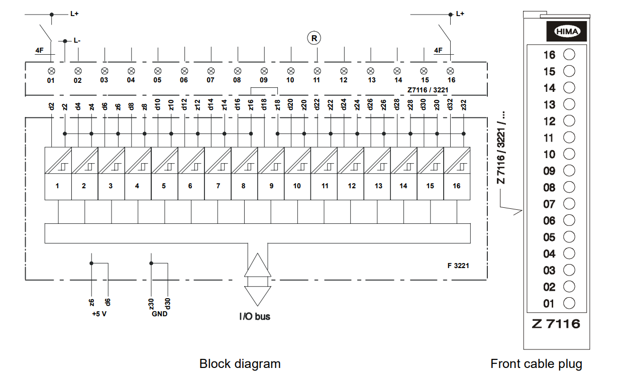
4.1 Signal Acquisition Mechanism
Each input channel receives signals from field devices through the front cable plug. When the input is a high level (24 V DC) or a mechanical contact is closed, the module's internal circuitry recognizes it as a logic "1"; otherwise, it is a logic "0". The module contains signal conditioning circuits that filter and shape the input signal to ensure it meets the system's processing requirements.
4.2 Electrical Isolation Principle
The module uses isolation components such as optocouplers or transformers to achieve electrical isolation between the input side and the system side. This design not only prevents interference caused by ground potential differences but also avoids damage to the control system from field-side faults.
4.3 Signal Processing Flow
Signal Input: Field signals are connected to the module via the Z 7116/3221 cable plug.
Signal Conditioning: The module filters and debounces the input signal to ensure stability.
Level Conversion: The 24 V DC field signal is converted to a 5 V TTL level recognizable by the system.
Status Latching: Within each scan cycle, the module latches the status of all channels and prepares them for upload.
Data Transmission: The status of all 16 channels is transmitted collectively to the F-IOP 01 module via the I/O bus.
4.4 Collaboration with the System Bus
The F 3221 itself does not have a system bus interface. Instead, it communicates via the I/O bus of its host rack with the F-IOP 01 module. The F-IOP 01 is responsible for aggregating data from all I/O modules in the same rack and exchanging safety data with the F-CPU 01 processor module via the system buses (Sys A / Sys B).
4.5 Watchdog and Safe State
Although the F 3221 itself does not have a Safety Integrity Level (SIL), within the HiQuad X system, its input data is processed by the F-CPU 01 within the safety cycle. If the system detects a communication interruption or module failure, it will trigger a safe state, causing output modules to enter a de-energized state, thereby ensuring system safety.
5. Installation and Wiring
5.1 Mechanical Installation
The F 3221 module is designed for standard 19-inch rack mounting and occupies a width of 4 TE. After insertion into the rack, the module receives its 5 V and 24 V power via the backplane.
5.2 Cable Connection
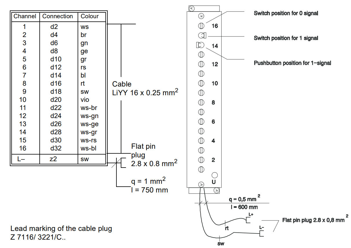
The matching Z 7116/3221 cable plug is used. Each cable contains 16 wires of 0.25 mm², corresponding to the 16 input channels and one common negative (L-). The wire color coding is as follows:
| Channel | Pin | Color Code |
| 1 | d2 | white (ws) |
| 2 | d4 | brown (br) |
| 3 | d6 | green (gn) |
| 4 | d8 | yellow (ge) |
| 5 | d10 | grey (gr) |
| 6 | d12 | pink (rs) |
| 7 | d14 | blue (bl) |
| 8 | d16 | red (rt) |
| 9 | d18 | black (sw) |
| 10 | d20 | violet (vio) |
| 11 | d22 | white-brown (ws-br) |
| 12 | d24 | white-green (ws-gn) |
| 13 | d26 | white-yellow (ws-ge) |
| 14 | d28 | white-grey (ws-gr) |
| 15 | d30 | white-pink (ws-rs) |
| 16 | d32 | white-blue (ws-bl) |
| L- | z2 | black (sw) |
6. Diagnostics and Maintenance
6.1 Status Indication
The module's front features channel status indicators, providing a visual display of the input status for each channel, which facilitates field debugging and fault diagnosis.
6.2 Test Functionality
Using a dedicated test plug, input signals can be simulated to verify channel functionality without the need to connect actual sensors.
6.3 Fault Handling
If a module or channel fails, the system can record and report the fault information through the HiQuad X diagnostic functions. The module supports online replacement for easy maintenance.
7. Application Scenarios
The F 3221 is suitable for the following industrial applications:
Sensor signal acquisition in safety control systems
Status monitoring of machinery and equipment (e.g., limit switches, emergency stop buttons)
Digital input processing in process automation
Fire alarm systems (when used with a certified system)