Foxboro
$500/360/360
In Stock
T/T
Xiamen
FBM207/B/C
Availability: | |
---|---|
Quantity: | |
Discrete inputs can be sensed across all the usual voltage levels found in industrial facilities. The FBM207/b/c uses one of the several termination assemblies (TAs) to match to the externally powered voltage level. In cases where the inputs are integral to the plant’s control scheme, the FBM207/b/c may be installed as a redundant pair with standard control blocks used to manage the redundancy.
The FBM207/b/c Voltage Monitor/Contact Sense Input Module functions as a 16-channel DC voltage monitor or 16-channel contact sensor. Each channel accepts a 2-wire input from a DC voltage source (FBM207) or pair of contacts or solid state switches (FBM207b/ FBM207c).
Associated (TAs) support discrete input signals at voltages of 60 VDC, 120 VAC/125 VDC, or 240 VAC. For voltages higher than 60 VDC, the TAs have additional signal conditioning hardware that provides voltage attenuation and optical isolation.
The module is available in three distinct types, and each type with its associated TA supports discrete inputs as shown below:
FBM207 | Provides voltage monitoring at: • 60 VDC • 120 VAC/125 VDC • 240 VAC Provides switch inputs with: • External 120 VAC/125 VDC • External 240 VAC |
FBM207b | 24 VDC Contact Sense |
FBM207c | 48 VDC Contact Sense |
Each discrete input is galvanically isolated from other channels and ground. Group isolated when used with external excitation.
The module performs signal conversion required to interface electrical input signals from field sensors to the redundant module Fieldbus. In addition, it executes programs for Discrete Input, Ladder Logic, Pulse Count, and Sequence of Events, with configurable options of Input Filter Time.
The module can be used as a single unit, or as a redundant pair (two FBM207s). When used as a redundant pair, the modules combine to provide redundancy at the Fieldbus Module (FBM) level, with field input signals received from one common termination assembly though a redundant adapter affixed to the baseplate of the FBM. The input current for redundant modules is doubled. A redundant digital input block in the Foxboro DCS Control Software validates each input in conjunction with information to/from the module, and selects the input with the highest quality for processing in the control strategy.
In a redundant configuration, contact sense power from each module is diode OR'd together in the redundant adapter to help assure redundant power.
A redundant contact input function block, CINR, is used for each redundant pair of inputs. The CINR block handles input reads and initialization logic for the redundant channels. On each execution cycle of the CINR block, identical reads are sent to both modules, fully exercising the fieldbus and the logic circuitry of each module.
Functional | ||
Communication | Communicates with its associated FCM or FCP via the redundant 2 Mbps module Fieldbus. | |
Input | 16 isolated and independent channels | |
Accuracy | Pulse Count: No missing pulses for pulse rate 0 to 250 Hz | |
Filter/Debounce Time | Configurable (No Filtering, 4, 8, 16, or 32 ms) NOTE: Digital filtering available for 200 Series FBM or competitive migration modules with version 1.25H or later firmware. | |
Voltage Monitor Function - Input | • Input: Logic One, On-State Voltage: 15 to 60 VDC Logic Zero, Off-State Voltage: 0 to 5 VDC Current: 1.4 mA (typical) at 5 to 60 VDC • Source Resistance Limits: Logic One, On-State: 1 kΩ (maximum) at 15 VDC Logic Zero, Off-State: 100 kΩ (minimum) at 60 VDC | |
Contact Sensor Function - Input | • Range (Each Channel): Contact open (off) or closed (on) • Open-Circuit Voltage: ◦ FBM207b: 24 VDC ±15% ◦ FBM207c: 48 VDC ±15% | |
Short-Circuit Current | 3.2 mA (typical) | |
Logic One, ON-State Resistance | 1.0 kΩ (maximum) | |
Logic Zero, OFF-State Resistance | 100 kΩ (minimum) | |
Power Requirements | • Input Voltage Range (Redundant): 24 VDC +5%, -10% • Consumption: ◦ FBM207 3 W ◦ FBM207b 4 W ◦ FBM207c 5 W • Heat Dissipation: ◦ FBM207 5.5 W (including contribution from field power supply) ◦ FBM207b 4 W ◦ FBM207c 5 W | |
Loop Power Supply Protection | Current limited at 3.2 mA (typical) | |
Calibration Requirements | Calibration of the module and termination assembly is not required. | |
Environmental | ||
Operating | Storage | |
Temperature | • FBM207/b/c: -20 to +70°C (-4 to +158°F) • Termination Assembly - PA: -20 to +70°C (-4 to +158°F) | -40 to +70°C (-40 to +158°F) |
Relative Humidity | 5 to 95% (noncondensing) | 5 to 95% (noncondensing) |
Altitude | -300 to +3,000 m (-1,000 to +10,000 ft) | -300 to +12,000 m (-1,000 to +40,000 ft) |
Vibration | 0.75g from 5 to 500 Hz | |
Contamination | Suitable for use in Class G3 (Harsh) environments as defined in ISA Standard S71.04, based on exposure testing according to EIA Standard 364-65, Class III. | |
NOTE: The environment ranges can be extended by the type of enclosure containing the module. See the PSS applicable to the enclosure to be used. | ||
Physical | ||
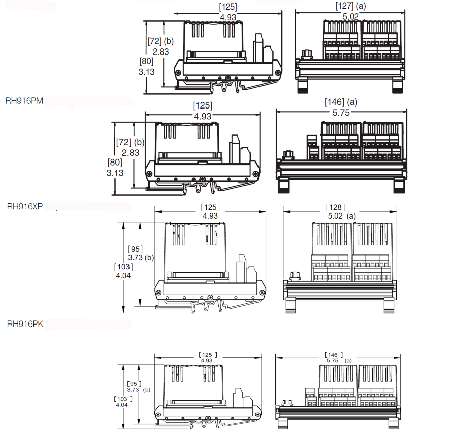
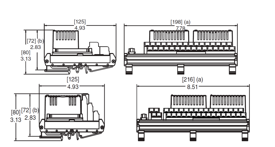
Mounting | • Module: FBM207/FBM207b/FBM207c mounts on a Modular baseplate. Baseplate can be mounted on a DIN rail (horizontally or vertically), or horizontally on a 19-inch rack using a mounting kit. Redundant modules must be located in odd and even adjacent positions on the baseplate (positions 1 and 2, 3 and 4, 5 and 6, or 7 and 8). See Standard 200 Series Baseplates (PSS 41H-2SBASPLT) for details. • Termination Assemblies (TAs): The TA mounts on a DIN rail and accommodates multiple DIN rail styles including 32 mm (1.26 in) and 35 mm (1.38 in). | |
Weight | • Module: 185 g (6.5 oz) approximate • Termination Assemblies: ◦ Compression Type: 127 mm (5.02 in) – 272 g (0.60 lb, approximate) 146 mm (5.75 in) – 317 g (0.7 lb, approximate) ◦ Ring Lug Type: 198 mm (7.78 in) – 400 g (0.90 lb, approximate) 216 mm (8.51 in) – 440 g (1.0 lb, approximate) | |
Dimensions - Module | • Height: 102 mm (4 in), 114 mm (4.5 in) including mounting lugs • Width: 45 mm (1.75 in) • Depth: 104 mm (4.11 in) | |
Part Numbers | • Module: ◦ FBM207: RH914TD ◦ FBM207b: RH914WH ◦ FBM207c RH917GY | |
Termination Cables | • Cable Lengths: Up to 30 m (98 ft) • Cable Materials: Polyurethane or Low Smoke Zero Halogen (LSZH) | |
Construction - Termination Assembly | • Material: Polyamide (PA), compression Polyamide (PA), ring lug • Family Group Color: Dark blue - discrete • Terminal Blocks: Inputs - 2 tiers, 16 positions Excitation - 2 tiers, 4 positions | |
Field Termination Connections | • Compression Accepted Wiring Sizes: ◦ Solid/Stranded/AWG: 0.2 to 4 mm2/0.2 to 2.5 mm2/24 to 12 AWG ◦ Stranded with Ferrules: 0.2 to 2.5 mm2 with or without plastic collar • Ring Lug Accepted Wiring Sizes: #6 size connectors (9.5 mm (0.375 in)) 0.5 to 4 mm2/22 AWG to 12 AWG |
Functional | ||
Communication | Communicates with its associated FCM or FCP via the redundant 2 Mbps module Fieldbus. | |
Input | 16 isolated and independent channels | |
Accuracy | Pulse Count: No missing pulses for pulse rate 0 to 250 Hz | |
Filter/Debounce Time | Configurable (No Filtering, 4, 8, 16, or 32 ms) NOTE: Digital filtering available for 200 Series FBM or competitive migration modules with version 1.25H or later firmware. | |
Voltage Monitor Function - Input | • Input: Logic One, On-State Voltage: 15 to 60 VDC Logic Zero, Off-State Voltage: 0 to 5 VDC Current: 1.4 mA (typical) at 5 to 60 VDC • Source Resistance Limits: Logic One, On-State: 1 kΩ (maximum) at 15 VDC Logic Zero, Off-State: 100 kΩ (minimum) at 60 VDC | |
Contact Sensor Function - Input | • Range (Each Channel): Contact open (off) or closed (on) • Open-Circuit Voltage: ◦ FBM207b: 24 VDC ±15% ◦ FBM207c: 48 VDC ±15% | |
Short-Circuit Current | 3.2 mA (typical) | |
Logic One, ON-State Resistance | 1.0 kΩ (maximum) | |
Logic Zero, OFF-State Resistance | 100 kΩ (minimum) | |
Power Requirements | • Input Voltage Range (Redundant): 24 VDC +5%, -10% • Consumption: ◦ FBM207 3 W ◦ FBM207b 4 W ◦ FBM207c 5 W • Heat Dissipation: ◦ FBM207 5.5 W (including contribution from field power supply) ◦ FBM207b 4 W ◦ FBM207c 5 W | |
Loop Power Supply Protection | Current limited at 3.2 mA (typical) | |
Calibration Requirements | Calibration of the module and termination assembly is not required. | |
Environmental | ||
Operating | Storage | |
Temperature | • FBM207/b/c: -20 to +70°C (-4 to +158°F) • Termination Assembly - PA: -20 to +70°C (-4 to +158°F) | -40 to +70°C (-40 to +158°F) |
Relative Humidity | 5 to 95% (noncondensing) | 5 to 95% (noncondensing) |
Altitude | -300 to +3,000 m (-1,000 to +10,000 ft) | -300 to +12,000 m (-1,000 to +40,000 ft) |
Vibration | 0.75g from 5 to 500 Hz | |
Contamination | Suitable for use in Class G3 (Harsh) environments as defined in ISA Standard S71.04, based on exposure testing according to EIA Standard 364-65, Class III. | |
NOTE: The environment ranges can be extended by the type of enclosure containing the module. See the PSS applicable to the enclosure to be used. | ||
Physical | ||
Mounting | • Module: FBM207/FBM207b/FBM207c mounts on a Modular baseplate. Baseplate can be mounted on a DIN rail (horizontally or vertically), or horizontally on a 19-inch rack using a mounting kit. Redundant modules must be located in odd and even adjacent positions on the baseplate (positions 1 and 2, 3 and 4, 5 and 6, or 7 and 8). See Standard 200 Series Baseplates (PSS 41H-2SBASPLT) for details. • Termination Assemblies (TAs): The TA mounts on a DIN rail and accommodates multiple DIN rail styles including 32 mm (1.26 in) and 35 mm (1.38 in). | |
Weight | • Module: 185 g (6.5 oz) approximate • Termination Assemblies: ◦ Compression Type: 127 mm (5.02 in) – 272 g (0.60 lb, approximate) 146 mm (5.75 in) – 317 g (0.7 lb, approximate) ◦ Ring Lug Type: 198 mm (7.78 in) – 400 g (0.90 lb, approximate) 216 mm (8.51 in) – 440 g (1.0 lb, approximate) | |
Dimensions - Module | • Height: 102 mm (4 in), 114 mm (4.5 in) including mounting lugs • Width: 45 mm (1.75 in) • Depth: 104 mm (4.11 in) | |
Part Numbers | • Module: ◦ FBM207: RH914TD ◦ FBM207b: RH914WH ◦ FBM207c RH917GY | |
Termination Cables | • Cable Lengths: Up to 30 m (98 ft) • Cable Materials: Polyurethane or Low Smoke Zero Halogen (LSZH) | |
Construction - Termination Assembly | • Material: Polyamide (PA), compression Polyamide (PA), ring lug • Family Group Color: Dark blue - discrete • Terminal Blocks: Inputs - 2 tiers, 16 positions Excitation - 2 tiers, 4 positions | |
Field Termination Connections | • Compression Accepted Wiring Sizes: ◦ Solid/Stranded/AWG: 0.2 to 4 mm2/0.2 to 2.5 mm2/24 to 12 AWG ◦ Stranded with Ferrules: 0.2 to 2.5 mm2 with or without plastic collar • Ring Lug Accepted Wiring Sizes: #6 size connectors (9.5 mm (0.375 in)) 0.5 to 4 mm2/22 AWG to 12 AWG |
(a) Overall width- for determining DlN rail loading.
(b) Height above DlN rail (add to DlN rail height for total)
(a) Overall width-for determining DlN rail loading.
(b) Height above DlN rail (add to DlN rail height for total).
(a) Overall width- for determining DlN rail loading.
(b) Height above DlN rail (add to DlN rail height for total)
(a) Overall width-for determining DlN rail loading.
(b) Height above DlN rail (add to DlN rail height for total).
content is empty!