Precision in machinery protection and condition monitoring relies fundamentally on matching the physical footprint and electromagnetic field of the sensor to the specific mechanical application. Selecting the correct proximity transducer size dictates the accuracy and reliability of your vibration and position data. When the probe size does not align with the target surface or expected movement, the entire monitoring system is compromised.
Choosing the incorrect probe introduces severe operational risks. A sensor that is too small for a large axial movement will truncate vibration data or trigger out-of-range errors during thermal expansion. Conversely, a sensor that is too large for a confined bracket or small shaft will suffer from side-viewing, cross-talk, and non-compliance with API 670 standards. These errors lead to false trips, missed mechanical faults, and catastrophic machinery failure.
This technical evaluation framework compares 5mm, 8mm, 11mm, and 25mm systems based on linear measuring range, shaft diameter, scale factor, and installation constraints to ensure accurate machinery diagnostics.
Probe tip diameter directly dictates the linear measuring range; larger tips (11mm, 25mm) provide longer sensing distances but require larger target areas and mounting clearances.
8mm proximity transducers serve as the industry default for standard radial vibration and axial position on shafts greater than 2 inches in diameter.
5mm probes are essential for confined spaces but offer a smaller linear range, whereas 25mm probes are reserved for extreme axial thrust or differential expansion where maximum range is critical.
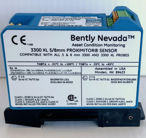
Proximity transducer size selection must account for the entire measurement chain, ensuring compatibility between the probe, extension cable, proximitor/driver, and the expected scale factor (sensitivity).
Table of Contents
Toggle
How Proximity Transducer Size Affects Vibration Monitoring
Defining "Size"
When engineers discuss probe dimensions, the millimeter designation refers specifically to the diameter of the probe tip. This is the encapsulated coil at the end of the sensor. It does not refer to the thread size of the probe body or the length of the integral cable. The tip diameter is the functional component that generates the electromagnetic field. A 3/8-24 threaded probe body can house an 8mm tip, just as a 1/4-28 body might house a 5mm tip. You must separate the mechanical mounting thread from the active sensing element.
Electromagnetic Field Dynamics
The coil diameter determines the shape and spread of the radio frequency (RF) field generated by the transducer. The proximitor drives a high-frequency alternating current (typically 1 to 2 MHz) through the extension cable and into the probe coil. This creates an oscillating magnetic field. When a conductive target material enters this field, eddy currents are induced on the surface of the metal. These eddy currents absorb energy from the RF field, decreasing the amplitude of the RF signal. A smaller coil produces a narrow, highly focused RF field. A larger coil generates a wider, more expansive field that penetrates slightly deeper and spreads further across the target surface.
The Size-to-Range Ratio
There is a direct engineering correlation between the probe tip diameter and its linear measuring range. A wider RF field yields a proportionally longer linear measuring range. You cannot cheat physics; if you need to measure a 10-millimeter gap, you cannot use an 8mm probe. However, this extended range comes with a physical trade-off. A wider field requires a wider, flatter target surface to avoid measurement errors. If the target area is smaller than the RF field footprint, the sensor will read inaccurately because the field wraps around the edges of the target.
Probe Tip Size
Typical Linear Range
Standard Scale Factor
Minimum Target Diameter
5mm
40 mils (1.0 mm)
200 mV/mil (8 V/mm)
1.0 inch (25.4 mm)
8mm
80 mils (2.0 mm)
200 mV/mil (8 V/mm)
2.0 inches (50.8 mm)
11mm
160 mils (4.0 mm)
100 mV/mil (3.94 V/mm)
3.0 inches (76.2 mm)
25mm
1000 mils (25.4 mm)
20 mV/mil (0.78 V/mm)
6.0 inches (152.4 mm)
Key Factors When Choosing Proximity Transducer Size
Required Linear Measuring Range (Sensing Distance)
The first step in selecting a probe is defining the expected movement of the target. Radial vibration typically involves small, high-frequency movements, usually measured in microns or peak-to-peak mils. Axial thrust or rotor position monitoring involves larger, slower shifts as the machine casing expands thermally or thrust bearings wear. The chosen probe must have a linear range that comfortably encompasses all expected dynamic movement, plus a safety margin for installation gapping.
You must keep the machine's maximum dynamic movement well within the sensor's linear region to avoid signal clipping. If a rotor shifts axially by 90 mils and you are using an 8mm probe with an 80-mil linear range, the sensor will drop off the linear curve. The proximitor output will flatline or become highly non-linear, masking actual machine movement and potentially preventing a critical machine trip.
Scale Factor and Sensitivity Variations
The scale factor defines how much voltage change occurs per unit of distance change. Standard 8mm and 5mm systems operate at a scale factor of 200 mV/mil (8 V/mm). This high sensitivity is ideal for precise radial vibration monitoring, where you are looking for minute changes in shaft dynamic motion. The monitoring system relies on this specific voltage-to-distance ratio to calculate vibration amplitude.
Larger probes operate at lower sensitivities to accommodate their extended measuring ranges within the standard -24Vdc power supply limitations. An 11mm system operates at 100 mV/mil, while a 25mm system operates at 20 mV/mil. The condition monitoring rack must be configured in software or hardware to match the specific scale factor of the chosen probe. If you connect an 11mm probe to a channel programmed for an 8mm probe, your vibration readings will be off by a factor of two.
Target Shaft Diameter and Curvature
Shaft curvature significantly affects the RF field. If a shaft is too small relative to the probe tip, the curved surface distorts the field. The standard rule dictates that 8mm probes require shafts greater than 2 inches in diameter. Smaller shafts require 5mm probes to maintain a relatively flat target area within the RF field footprint. When you mount a flat-faced probe against a highly curved surface, the distance from the probe face to the shaft varies drastically across the diameter of the coil.
When a probe is too large for a small shaft, "side-viewing" occurs. The RF field wraps around the curvature of the shaft, interacting with the sides rather than just the top surface. This leads to inaccurate gap voltages, scale factor errors, and unreliable vibration data. The sensor begins measuring the sides of the shaft, which may have different runout characteristics or keyways, introducing massive glitches into the vibration signal.
Physical Mounting Constraints and Clearances
Machine casings, bearing housings, and available tapped holes present strict physical limitations. You must ensure adequate physical space to install, gap, and lock down the probe without interference. In many integrally geared compressors or small pumps, the bearing housing simply does not have enough metal to drill and tap a hole for a 3/8-24 or M10 thread, forcing the use of smaller 1/4-28 or M8 threaded 5mm probes.
A critical installation requirement is the "counterbore" clearance. This is the minimum metal-free zone required around the probe tip. If the surrounding metal bracket or casing is too close to the tip, the RF field will interact with it instead of the target shaft. This causes severe measurement errors, effectively reducing the linear range and altering the scale factor. Larger probes require significantly larger counterbore clearances. A 25mm probe requires a massive metal-free zone, often necessitating custom mounting brackets or extensive machining of the machine casing.
Target Material and Electrical Runout
The metallurgy of the target shaft interacts differently with the transducer's RF field. Systems are factory calibrated for AISI 4140 steel. If the target material differs—such as 17-4 PH stainless steel, Inconel, or K-Monel—the system must be recalibrated to ensure accurate scale factors. Different metals have different magnetic permeabilities and electrical conductivities, which change how the eddy currents form and dissipate.
Larger probes, due to their wider RF field, can average out minor surface imperfections or mechanical runout better than smaller probes. However, this wider field also makes them more susceptible to broader electrical runout variations across the shaft surface. Electrical runout occurs when the metallurgical properties of the shaft are not uniform, causing the probe to see a change in gap even when the shaft is perfectly round. You must burnish and degauss the target area to minimize these effects.
5mm vs. 8mm vs. 11mm vs. 25mm Proximity Transducers
5mm Proximity Transducers: Tight Clearances and Smaller Shafts
The 5mm proximity transducer is designed for applications where space is severely limited. Primary use cases include fractional horsepower motors, small compressors, turbochargers, and machinery with small shaft diameters. They are essential when an 8mm probe would suffer from side-viewing due to shaft curvature or when the bearing housing lacks the mass to support a larger drilled hole.
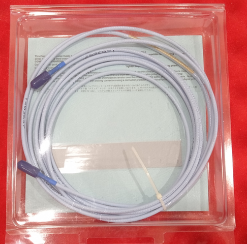
The performance profile of a 5mm probe includes the shortest linear measuring range (typically 40 mils) and a highly focused RF field. Many 5mm probes are designed to interface seamlessly with standard 8mm extension cables and proximitors. This maintains standard system lengths (5 meters or 9 meters) without requiring proprietary cabling, allowing plants to standardize their inventory while accommodating tight physical clearances on specific machines.
8mm Proximity Transducers: The Industry Standard
The 8mm proximity transducer is the undisputed industry standard. It is the default choice for standard API 670 applications, general-purpose machinery, and critical assets like steam turbines, large centrifugal pumps, and axial compressors. Unless specific mechanical constraints dictate otherwise, the 8mm probe is the baseline for any condition monitoring program.
This size offers the optimal balance between a useful linear range (typically 80 mils or 2mm) and a manageable physical footprint. It provides sufficient range for most radial vibration and standard axial position monitoring tasks while fitting comfortably into standard bearing housings. The 8mm system is the most heavily supported size across all major condition monitoring hardware platforms.
11mm Proximity Transducers: Extended Range Requirements
When the expected movement exceeds the linear range of an 8mm probe, the 11mm proximity transducer is the next logical step. Primary use cases include axial position monitoring on large thrust bearings, where thermal growth and thrust wear can cause the rotor to shift significantly. They are also used on large fans and cooling tower gearboxes where structural vibration requires a larger standoff distance.
The 11mm probe provides an extended sensing distance, typically around 160 mils (4mm). This increased range requires a correspondingly larger target area and a wider counterbore clearance. The increased physical size limits mounting options in standard, tight bearing housings. You must verify that the target collar or shaft end is wide enough to fully encompass the 11mm RF field throughout the entire range of axial movement.
25mm Proximity Transducers: Maximum Sensing Distance
The 25mm proximity transducer is reserved for extreme applications requiring maximum sensing distance. Primary use cases include monitoring differential expansion on large steam turbines, massive hydro-turbines, and extreme axial shift scenarios. In these applications, the rotor expands thermally at a different rate than the casing, resulting in massive relative movement.
These probes offer a massive linear range, often up to 1000 mils (25.4mm) or more. Implementation risks are significant. They require substantial structural mounting considerations, massive metal-free zones, and heavy-duty brackets to prevent bracket resonance. Furthermore, the massive RF field spread makes them highly sensitive to target surface irregularities, adjacent metal structures, and even the geometry of the collar they are observing.
Proximity Transducer Installation Risks and Compatibility Checks
Cross-Talk and Minimum Sensor Spacing
Cross-talk occurs when the RF fields of two adjacent probes interfere with one another, causing beat frequencies and erratic readings. This is a common issue when mounting X and Y radial vibration probes close together in a tight bearing housing. The proximitors operate at slightly different frequencies due to manufacturing tolerances, and when the fields overlap, they create a low-frequency beat that appears as massive vibration on the monitoring system.
Minimum separation distances are dictated by the probe size. 8mm probes require less separation than 11mm or 25mm probes. If close mounting is unavoidable due to casing constraints, mitigation strategies include staggering the mounting planes axially along the shaft. Alternatively, you can order proximitors with specifically tuned, offset oscillator frequencies to prevent the beat frequency from falling within the machine's operational bandwidth.
Cable Lengths and Proximitor Matching
A proximity transducer system is a tuned electrical circuit consisting of three parts: the probe, the extension cable, and the proximitor. The total electrical length must match the proximitor's calibration, typically 5.0 or 9.0 meters (16.4 or 29.5 feet), regardless of the probe tip size. The proximitor relies on the specific capacitance and resistance of that exact cable length to maintain the oscillator circuit.
Mixing mismatched components is a critical error. Driving an 11mm probe with an 8mm proximitor immediately voids the calibration and results in an incorrect scale factor. Using a 5-meter proximitor with a 9-meter cable system will shift the linear range and alter the sensitivity. The entire measurement chain must be matched, verified, and calibrated as a complete system before installation.
Environmental Factors, Armor, and Accessories
Harsh environments dictate physical protection requirements. High pressure, corrosive gases, and extreme temperatures require robust sensor construction. Larger probes generally offer more robust physical housings, but all sizes can be specified with protective accessories. You must evaluate the routing path from the machine casing to the junction box.
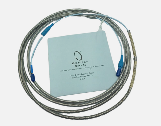
Consider the use of heavy-duty armored cables versus standard unarmored cables based on the routing environment. Armor prevents crushing and abrasion during maintenance activities. Fluid and gas sealing options, such as cable seal glands or high-pressure feedthroughs, are critical when probes penetrate pressurized casings. Ensure the chosen probe size has the necessary environmental ratings, including hazardous area certifications (e.g., ATEX, CSA) for your specific application.
System Verification and Calibration Checks
Post-installation verification is a critical step before commissioning the machinery. You must confirm that the installed system operates correctly and matches the expected scale factor for the specific probe size and target material. Relying solely on factory calibration certificates is insufficient for critical machinery protection.
Use a spindle micrometer and a sample of the exact target material to step the probe through its linear range. Record the output voltage at 10-mil increments to confirm the scale factor (e.g., 200 mV/mil for an 8mm probe). Plot these values to ensure the curve is linear and that the installation gap places the sensor exactly in the center of its linear range. This physical verification ensures the monitoring rack will interpret the voltage signals accurately and trip the machine when necessary.
Conclusion
Selecting the correct proximity transducer size is a strict mechanical and electrical requirement dictated by target size, expected movement, scale factor requirements, and mounting space. Start your selection process with the 8mm probe as the baseline standard. Downsize to 5mm only if space or shaft diameter forces the issue. Upsize to 11mm or 25mm only when axial movement or differential expansion exceeds the linear range of the 8mm system.
Established in 2010, Exstar is a professional supplier of industrial automation spare parts, supporting applications involving sensing systems, turbine supervisory instrumentation, distributed control systems, turbine control, emergency shutdown systems, and programmable logic controllers. Its engineering-led sales team assists customers with system architecture proposals, part-number selection, system testing, and after-sales service, helping buyers source compatible automation components with greater confidence.
Consult OEM machinery manuals to determine expected vibration and thrust tolerances before selecting a probe size.
Measure available mounting clearances and counterbore dimensions to ensure the chosen probe will not suffer from side-viewing interference.
Verify that the entire measurement chain (probe, cable, proximitor) is matched and compatible with your existing condition monitoring rack configurations.
Perform a physical calibration check using a spindle micrometer prior to machinery startup to confirm the scale factor.
FAQ
Q: Can I use a 5mm proximity probe with an 8mm extension cable?
A: Yes, many manufacturers design 5mm probes to interface seamlessly with standard 8mm extension cables and proximitors. This allows you to maintain standard system lengths without needing proprietary cabling, simplifying inventory and installation.
Q: Why is the 8mm probe considered the industry standard?
A: The 8mm probe offers the optimal balance of linear measuring range (typically 80 mils) and physical footprint. It complies with API 670 standards and fits comfortably into most standard bearing housings while providing sufficient range for typical radial vibration monitoring.
Q: What happens if I use an 11mm probe on a small 1-inch shaft?
A: Using a large probe on a small shaft causes side-viewing. The wide RF field wraps around the shaft curvature, interacting with the sides rather than just the top surface. This distorts the measurement, leading to inaccurate gap voltages and incorrect vibration readings.
Q: How do I know if I need a 25mm proximity transducer?
A: A 25mm probe is required when the expected target movement exceeds the linear range of smaller probes. This is typical in extreme axial shift monitoring or differential expansion measurements on massive machinery like large steam turbines, where movement can exceed 1000 mils.
Q: Does the probe size affect the scale factor (sensitivity)?
A: Yes, probe size directly impacts the scale factor. Smaller probes (5mm, 8mm) typically operate at a highly sensitive 200 mV/mil. Larger probes (11mm, 25mm) operate at lower sensitivities (e.g., 100 mV/mil or 20 mV/mil) to accommodate their extended linear measuring ranges.
Q: What is counterbore clearance and why does it matter?
A: Counterbore clearance is the minimum metal-free zone required around the probe tip. If the surrounding mounting bracket or casing is too close, the RF field interacts with it instead of the target shaft, causing severe measurement errors. Larger probes require larger counterbore clearances.
Q: Can I mix an 11mm probe with an 8mm proximitor?
A: No. A proximity transducer system is a tuned electrical circuit. Mixing mismatched components, such as driving an 11mm probe with an 8mm proximitor, immediately voids the calibration, results in an incorrect scale factor, and renders the vibration data useless.