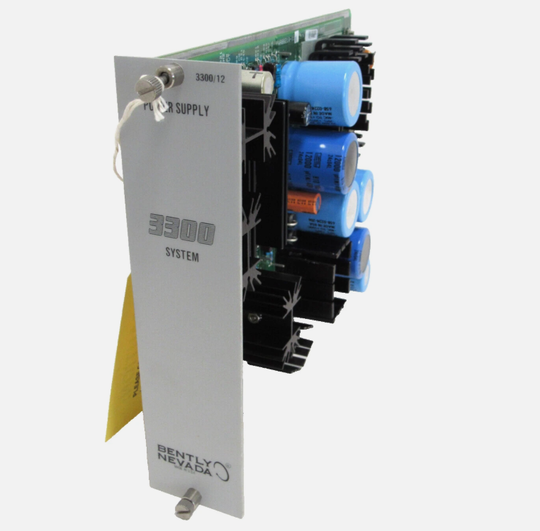
Unplanned downtime and catastrophic machinery failure often stem from a single point of failure: a lost or degraded signal from a critical vibration monitoring system. When a proximity transducer system drops its signal, reliability teams must immediately determine if the issue is a genuine mechanical fault, such as extreme bearing wear or shaft failure, or an instrumentation error, like a sensor failure or cable short. False trips cost production time. Ignored signal loss risks asset destruction.
Systematically isolating the fault within the transducer system—specifically the probe, extension cable, and Proximitor® sensor—is the only way to restore reliable monitoring without replacing unnecessary components. This guide provides a strict, evidence-based diagnostic framework for resolving signal loss.
Systematic Isolation: Signal loss troubleshooting must follow a reverse-path methodology, starting at the monitor rack, moving to the interconnect wiring, checking the Proximitor, testing the extension cable, and ending at the probe tip.
DC Gap Voltage is the Baseline: Before analyzing AC vibration signals, verifying the DC gap voltage (-8 to -12 Vdc standard) is mandatory to confirm the probe is within its linear range and the circuit is intact.
System Length Matching: A primary cause of calibration failure and signal degradation is mismatched electrical lengths (e.g., combining a 1-meter probe with a 4-meter cable on a 9-meter Proximitor).
Component Replacement: Probes and cables are consumable and prone to mechanical damage; Proximitors are highly reliable but susceptible to ground loops and improper mounting. Blindly replacing the probe rarely resolves complex signal issues.
Table of Contents
Toggle
Structure of the Proximity Transducer System
Field diagnostics require a complete grasp of how the monitoring hardware interacts. A functional proximity transducer system relies on a precise electrical balance between three interdependent components. If any single component degrades, the entire monitoring channel fails to provide accurate machinery protection data. You cannot troubleshoot a loop if you do not understand the baseline electrical characteristics of its parts.
The Three-Part Architecture
The standard configuration consists of an eddy current sensor, a specific-length extension cable, and the signal-conditioning sensor. The Bently Nevada 3300 XL system operates as a tuned resonant circuit. The probe contains a precisely wound coil of wire encapsulated in a durable plastic tip, usually made of polyphenylene sulfide (PPS). The extension cable connects this coil to the Proximitor, which houses the oscillator and demodulator electronics. The Proximitor generates a high-frequency radio frequency (RF) signal, sends it through the coaxial cable to the probe coil, and measures the resulting impedance changes.
The physical construction of these components dictates their failure modes. Probes live inside the machine casing, exposed to hot oil, extreme temperatures, and flying debris. Extension cables route through external conduits where they suffer from vibration chafing, crushed piping, and fluid ingress. Proximitors sit in junction boxes, generally safe from mechanical damage but highly vulnerable to ground loops, loose terminal connections, and heat soaking if the enclosure lacks ventilation.
The Eddy Current Principle and Scale Factor
Eddy current proximity probes measure shaft displacement by detecting changes in the electromagnetic field between the probe tip and a conductive target. The Proximitor converts these changes into a voltage signal. A common calibration scale factor is 200 mV/mil (7.87 V/mm), allowing accurate vibration and shaft position measurements.
Defining Signal Loss
Signal loss can result from power failures, damaged cables, incorrect probe gaps, or electrical interference. Common symptoms include complete signal loss, abnormal gap voltage, and intermittent readings. Identifying the specific fault condition helps technicians locate the problem and avoid unnecessary component replacement.
Success Criteria for Troubleshooting
Effective proximity probe troubleshooting focuses on accurately identifying electrical faults, signal interference, and component failures. Technicians should verify power supply, cable continuity, probe gap, and signal stability before replacing parts. Systematic testing helps reduce downtime, improve measurement reliability, and maintain compliance with applicable API 670 requirements.
Basic Fault Isolation Steps
Effective troubleshooting demands a reverse-path methodology. Starting at the field sensor often leads to wasted effort if the actual fault lies in the control room wiring or the monitor rack power supply. The following framework systematically eliminates variables from the control room down to the machine casing.
Verifying the Power Supply
The first step at the field junction box is checking the power input at the Proximitor. The system requires a stable, clean power source, typically -24 Vdc. Use a digital multimeter (DMM) set to DC voltage. Place the black lead on the COM (common) terminal and the red lead on the VT (power) terminal of the Proximitor. A fluctuating, low, or absent supply voltage mimics a probe failure. If the supply voltage is outside the -23 to -24 Vdc range, the issue lies upstream in the monitor rack power supply or the interconnect wiring. Do not proceed with sensor testing until you establish a clean -24 Vdc supply.
Measuring DC Gap Voltage
Before analyzing AC vibration signals, verifying the DC gap voltage is mandatory. This voltage confirms the probe is within its linear range and the electrical circuit is intact. Measure the DC voltage between the OUT and COM terminals on the Proximitor.
DC Voltage Reading
Diagnostic Indication
Common Field Causes
0 Vdc to -1 Vdc
Short Circuit or Power Loss
Crushed extension cable, shorted probe coil, missing -24Vdc supply from the rack.
-8 Vdc to -12 Vdc
Normal Operation
System is healthy; probe is gapped correctly. Look for AC noise if alarms persist.
Loose SMA coaxial connector, ground loop, turbine oil or water ingress in connectors.
Monitor Rack vs. Field Instrumentation
If the field measurements at the Proximitor are normal but the control room still shows a signal loss, you must isolate the monitor rack. Disconnect the field wiring at the monitor rack (such as a 3500 series rack) and measure the incoming signal directly at the landed wires. If the signal is healthy at the wire ends but the rack channel shows a fault, the monitor card or rack backplane requires replacement or reconfiguration. This step prevents sending technicians into hazardous field environments unnecessarily.
Inspecting Interconnect Cables
Before blaming the field transducer, verify the interconnect wiring between the Proximitor and the monitor rack. Terminal block corrosion, loose field wiring, or damaged shielding often mimics a sensor failure. Perform a continuity check on the field wiring using a twisted pair shielded cable standard. Ensure the shield drain wire is properly grounded at one end only—typically at the monitor rack instrument ground bus. Grounding the shield at both the rack and the field junction box creates a ground loop that will severely degrade the signal with 50/60Hz line noise.
Step-by-Step Troubleshooting for the Transducer System
Once you confirm the power supply is stable and the interconnect wiring is intact, you must evaluate the three core components of the transducer system. Follow these phases sequentially to isolate the exact point of failure.
Phase 1: Evaluating the Proximitor Sensor
To determine if the Proximitor is the source of the failure, you must isolate it from the field cables. A failed oscillator circuit inside the Proximitor will output a dead signal regardless of the probe's condition.
Disconnect the extension cable from the Proximitor's coaxial connector. Leave the field wiring (VT, OUT, COM) connected.
Ensure the -24 Vdc power is still applied to the VT and COM terminals.
Measure the output voltage between the OUT and COM terminals using your DMM.
An isolated, healthy Proximitor with no cable attached will typically output a voltage very close to the supply voltage, usually between -22 and -24 Vdc. If the output reads 0 Vdc or a very low voltage while disconnected, the internal circuitry of the Proximitor has failed. Replace the unit.
Phase 2: Testing the Extension Cable
Extension cables operate in harsh environments and are highly susceptible to mechanical damage and fluid ingress. Use a digital multimeter to perform continuity and resistance checks. You must disconnect both ends of the cable to test it properly.
Continuity and Resistance Check: Disconnect the cable from the Proximitor and the probe. Measure the resistance of the center conductor from end to end. A standard extension cable will typically measure around 0.22 ohms per meter. Next, measure the outer shield resistance end to end, which should be around 0.06 ohms per meter. High resistance indicates a failing crimp or corroded pin.
Short Circuit Check: Measure resistance between the center pin and the outer shield on the same end of the cable. It should read open (infinite resistance). Any measurable resistance indicates a short, likely caused by crushed conduits driving the shield into the core wire, or degraded Teflon insulation.
Visual Inspection: Inspect the miniature coaxial connectors. Look for oil degradation, improper torque, or missing insulation tape. The connectors must be tightened to the manufacturer's specific torque rating. A loose connector introduces high resistance, shifting the DC gap voltage and causing false trips.
Phase 3: Inspecting the Probe
If the Proximitor and extension cable pass all tests, shift focus to the Bently Nevada 3300 XL Probe mounted on the machine casing. This requires physical access to the machine, which may require a permit or a brief outage.
Begin with a physical inspection. Look for tip damage caused by rubbing against the shaft. Check for cable chafing at the reverse mount or standard mount exit. Signs of extreme heat degradation, such as brittle, cracked, or discolored cabling, indicate the probe has operated outside its thermal limits and must be replaced.
Next, perform resistance checks on the probe's internal coil. Disconnect the probe from the extension cable. Measure the resistance between the center pin and the outer shield of the probe's connector. The standard resistance ranges vary based on the physical length of the probe's integral cable. For example, a 1-meter probe will have a different baseline resistance than a 0.5-meter probe. Always check these measurements against the manufacturer's specification sheet. A reading of infinite ohms means the internal coil is broken. A reading of zero ohms means the coil is shorted.
Target material verification is also essential. Changes in the observed shaft material will cause apparent signal loss or severe calibration errors. If maintenance teams replaced a rotor shaft with a different alloy, the altered electrical runout and magnetic properties will invalidate the 200 mV/mil scale factor. The system must be recalibrated for the new target material using a specialized target material simulator.
Phase 4: Analyzing the AC Signal Component
AC signal analysis helps identify vibration abnormalities and electrical interference after confirming a stable DC gap voltage. Technicians can use a vibration analyzer or oscilloscope connected to the Proximitor's BNC output to examine signal quality. Distorted waveforms, unusual spikes, or 50/60 Hz noise may indicate grounding problems, damaged shielding, or shaft runout.
Common Causes of Signal Degradation and False Trips
Ghost Readings on Tripped Machines
Ghost vibration readings occur when monitoring systems display vibration despite the machine being stationary. Common causes include electrical interference, grounding faults, and signal processing issues. Checking field wiring, grounding connections, and monitor settings helps identify false readings before replacing the proximity probe.
Environmental Ingress
Moisture, oil, and chemical contamination can affect proximity probe connectors and signal transmission. Contaminated or poorly sealed connections may cause unstable voltage readings and intermittent signal loss. Proper connector protection, compatible sealing materials, and regular inspections help maintain reliable sensor performance.
Improper Gap Setting and Thermal Growth
Incorrect probe gap settings can cause signal loss when machinery expands during operation. Thermal growth changes the distance between the probe tip and the shaft, potentially moving the sensor outside its calibrated linear range. Setting the gap according to manufacturer specifications and accounting for thermal expansion helps maintain measurement accuracy.
Part Replacement and System Calibration Rules
The System Length Rule
Proximity probe system length must match the Proximitor's calibrated configuration. Common systems use 5-meter or 9-meter total cable lengths, including the probe cable and extension cable. Incorrect combinations can affect signal sensitivity and measurement accuracy. Always verify component compatibility and part numbers before replacement.
Repair vs. Replace Economics
Damaged proximity probes and extension cables should generally be replaced rather than spliced or repaired in the field. Cable modifications can alter electrical characteristics and compromise calibration. Maintaining compatible spare components helps reduce downtime and prevent unnecessary machinery trips.
Post-Replacement Verification
Post-replacement testing confirms that the proximity measurement system operates correctly. Technicians should verify DC gap voltage, check probe linearity against the applicable calibration specification, and confirm normal monitor status. Accurate verification helps restore reliable vibration monitoring and machinery protection.
Conclusion
Measure the Proximitor power supply immediately to confirm a stable -24 Vdc source before dismantling any field wiring.
Record the DC gap voltage at the OUT and COM terminals to determine if the fault is a short circuit, open circuit, or out-of-range gap.
Isolate the fault by disconnecting the extension cable and testing the Proximitor, cable, and probe independently using a digital multimeter.
Verify that the total electrical length of the replacement probe and extension cable exactly matches the Proximitor's calibrated length (5 meters or 9 meters).
FAQ
Q: What is the standard gap voltage for a proximity probe?
A: The standard DC gap voltage for most industrial proximity probes is typically between -8 and -12 Vdc. This ensures the sensor operates in the center of its linear range, allowing accurate measurement of both positive and negative shaft vibration without clipping the signal.
Q: Can I splice a damaged extension cable to restore the signal?
A: No. Splicing a proximity probe extension cable is strictly prohibited. Splicing alters the electrical impedance and capacitance of the tuned resonant circuit, which destroys the calibration scale factor and renders the vibration measurements highly inaccurate.
Q: Why does my monitor show vibration when the machine is completely stopped?
A: Ghost readings on a static machine are usually caused by electrical noise, ground loops, or residual magnetism in the rotor shaft, known as electrical runout. It rarely indicates a failed probe. You must identify and eliminate the source of the electrical interference.
Q: How do I know if my Proximitor sensor has failed?
A: Disconnect the extension cable from the Proximitor and measure the DC output voltage while ensuring -24 Vdc power is supplied. If the output voltage drops to 0 Vdc or is severely degraded without a cable attached, the internal circuitry has failed.
Q: What happens if I mix a 5-meter probe system with a 9-meter Proximitor?
A: Mismatching system lengths will cause immediate calibration failure. The system will not produce the standard 200 mV/mil scale factor, the DC gap voltage will be incorrect, and the monitor will likely register an out of OK fault or display wildly inaccurate vibration data.
Q: How often should proximity transducer systems be calibrated?
A: Proximity systems should undergo a linearity check and verification during major machine turnarounds or at least every 3 to 5 years. If a component is replaced or the shaft material changes, immediate recalibration and verification are mandatory.