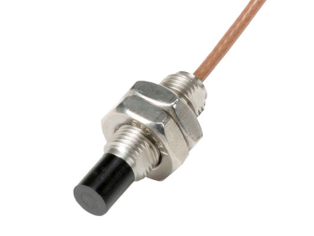
Turbomachinery condition monitoring operates in a zero-margin-for-error reality. Undetected rotor vibration or shaft displacement in rotating equipment rapidly escalates into catastrophic mechanical failure. Plant engineers and reliability teams face a strict decision when specifying non-contact displacement sensors: choosing between standard 8mm and extended-range 16mm profiles. This selection process relies entirely on machine scale, target area geometry, and the required measurement range.
The Emerson/Epro PR6423 (8mm) and PR6424 (16mm) series stand as industry-standard solutions for Machine Monitoring Systems (MMS). Deciding on the correct sensor profile demands a technical evaluation of spatial constraints, shaft diameter, and dynamic displacement expectations. When comparing PR6423 vs PR6424, engineers must align the sensor's electromagnetic field characteristics with the physical realities of the machine casing and rotor dynamics.
Measurement Range Dictates Selection: The 16mm PR6424 offers a significantly larger linear measurement range compared to the 8mm PR6423, making it mandatory for large-scale hydro or steam turbines with high expected shaft movement.
Spatial Constraints and Clearances: The PR6423 is required for tighter machine casings and smaller target areas where a 16mm sensor would suffer from side-viewing interference or physical mounting conflicts.
Target Shaft Diameter: Sensor selection must align with the shaft's diameter; 16mm sensors require a larger continuous target area to maintain a uniform magnetic field and ensure linear output.
System Compatibility & Asset Optimization: Both sensors require matching drivers/converters and extension cables calibrated to the specific sensor head size and target material to function correctly within broader plant asset optimization and machinery protection systems.
Table of Contents
Toggle
How to Choose the Right Eddy Current Sensor
Operating Principle (Magnetic vs. Capacitive)
Eddy current technology remains the absolute standard for turbomachinery protection. Unlike capacitive sensors that rely on capacitance changes and suffer severe signal degradation from oil, dirt, or moisture, eddy current sensors utilize high-frequency magnetic fields. A driver generates a radio frequency signal that travels through the extension cable to the sensor coil. This creates an alternating magnetic field at the sensor tip. When this field intersects a conductive target like a steel rotor shaft, it induces eddy currents on the surface of the metal. These eddy currents absorb energy from the sensor's magnetic field, decreasing the amplitude of the RF signal. The driver demodulates this amplitude change into a proportional DC voltage. This allows them to measure shaft displacement accurately through lubricating oil, water, and harsh industrial contaminants without losing signal integrity. Capacitive sensors simply cannot survive inside a wet, oil-flooded bearing housing.
Defining the Measurement Objective
Sensor selection begins with defining the exact measurement objective. Monitoring high-frequency radial vibration on a high-speed compressor shaft typically requires the focused field of a smaller sensor. You are looking at dynamic movement in the micron or mil range. Conversely, measuring large-scale static or dynamic shaft displacement, such as axial thrust position on a massive turbine rotor, demands the extended linear range provided by a larger sensor face. Thrust wear can allow a rotor to shift several millimeters before catastrophic rubbing occurs. An 8mm sensor will drop out of its linear range long before a large steam turbine reaches its alarm setpoint for axial position.
Target Area Geometry
A fundamental rule of thumb governs eddy current sensor application: the target area must be at least 2.5 to 3 times the diameter of the sensor tip. This prevents edge effects, where the magnetic field wraps around the curvature of the shaft or detects adjacent geometric features like keyways, oil holes, or shaft shoulders. If the field sees anything other than a flat, continuous surface, you get non-linear and highly inaccurate readings. For an 8mm sensor, you need a minimum track width of about 24mm. For a 16mm sensor, you need a massive 48mm track. If you mount a 16mm sensor over a narrow collar, the field spills over the edges, and the driver output becomes useless.
Environmental Survivability
Both the 8mm and 16mm profiles are engineered for extreme environments. Baseline expectations include resistance to high temperatures, continuous oil submersion, and pressurized environments typical in critical compressors, boiler feed pumps, and forced draft fans. The robust construction ensures long-term stability under continuous mechanical stress. The sensor tips are typically molded from high-performance plastics like PPS (Polyphenylene Sulfide) or PEEK, which resist chemical attack from synthetic lubricants and ammonia. The threaded cases are usually 300-series stainless steel. When installing these in pressurized environments, you must use proper fluid seals or cable glands to prevent oil from wicking up the cable jacket and leaking outside the machine casing.
PR6423 8mm Eddy Current Sensor: Features and Best Uses
Design Profile
The PR6423 features a compact 8mm tip diameter, producing a tightly focused electromagnetic field. This physical footprint provides a standard linear measurement range optimized for standard radial vibration and phase reference (Keyphasor) monitoring. The smaller profile allows for installation in restrictive machine casings. The standard linear range is typically 2mm (80 mils). The standard sensitivity is 8 mV/um (200 mV/mil). This means for every mil of shaft movement, the driver output changes by 200 millivolts. The sensor case usually features an M10x1 or 3/8-24 thread, allowing it to thread directly into standard bearing housings or internal mounting brackets.
Ideal Use Cases
This 8mm sensor excels in medium-to-small turbomachinery. Typical applications include high-speed centrifugal compressors, boiler feed pumps, forced draft fans, and smaller gas or steam turbines. In these environments, shaft diameters are smaller, and expected displacement amplitudes remain within the sensor's standard linear range. When setting up a phase reference, the 8mm sensor is ideal for detecting the sharp voltage drop caused by a standard keyway passing under the tip. The focused field provides a crisp, clean pulse that the monitoring system uses to calculate RPM and phase angle.
Performance Limitations
The primary constraint of the 8mm profile is its limited linear range. It cannot track extreme axial shifts or operate at large standoff distances. If a machine experiences a massive transient shift, an 8mm sensor mounted too close risks physical contact (rubbing) with the shaft, while one mounted too far will lose signal linearity entirely. If you gap an 8mm sensor at -10 Vdc (center of the linear range), you only have about 1mm of movement in either direction before the signal flattens out. On a large hydro turbine where thermal growth and hydraulic forces can shift the shaft by 3mm, the 8mm sensor is completely inadequate.
Installation Best Practices for 8mm Sensors
Verify the target material matches the calibration curve of the driver (typically 4140 steel).
Ensure the mounting bracket is rigid and has a natural frequency at least ten times higher than the machine's running speed.
Set the initial mechanical gap using a feeler gauge, typically around 1.0mm to 1.2mm, before fine-tuning with a multimeter.
Torque the locknut to the manufacturer's specification to prevent the sensor from backing out under high vibration.
Route the integral cable away from sharp edges and secure it with tie-downs to prevent fretting damage to the jacket.
PR6424 16mm Eddy Current Sensor: Features and Best Uses
Design Profile
The PR6424 utilizes a 16mm tip diameter, generating a significantly larger and deeper electromagnetic field. This extended field translates directly into a longer linear measurement range, allowing the sensor to accurately track displacement over a much greater distance without signal distortion. The standard linear range for a 16mm sensor is typically 4mm (160 mils) or even up to 8mm depending on the specific driver configuration. Because the range is larger, the sensitivity is lower, usually around 4 mV/um (100 mV/mil). The threaded case is larger, often M18x1.5 or 5/8-18, requiring larger tapped holes in the machine casing.
Ideal Use Cases
The 16mm profile is mandatory for applications requiring high standoff distances or the ability to track large displacement amplitudes. Heavy-duty gas turbines, large steam turbines, and hydro turbine guide bearings frequently utilize the PR6424 to monitor axial thrust and massive radial movements where an 8mm sensor would fail to capture the full range of motion. In hydro applications, the sheer mass of the water and the rotor can cause significant low-frequency runout. The 16mm sensor can be gapped further away from the shaft, providing a safety margin against physical contact while still maintaining a linear output across the entire range of movement.
Spatial and Mounting Considerations
Deploying a 16mm sensor introduces distinct physical challenges. It requires larger mounting brackets, increased side clearances to prevent side-viewing interference, and a larger counterbore diameter. Retrofitting a PR6424 into older, compact machine casings designed for smaller sensors often requires significant machining and engineering modifications. If you try to thread a 16mm sensor into a deep, narrow counterbore originally drilled for an 8mm sensor, the magnetic field will interact with the walls of the counterbore. This side-viewing effect will drastically alter the scale factor and render the measurements invalid. You must machine the counterbore to a minimum diameter of 32mm to 40mm to clear the field.
Bracket Design for Large Sensors
When mounting 16mm sensors internally, bracket design is critical. Because the sensor is heavier and the standoff distance is larger, the bracket acts like a diving board. If the bracket is too thin or too long, it will resonate at the machine's running speed. The monitoring system will read this bracket vibration as shaft vibration, leading to false alarms and unnecessary machine trips. Brackets for 16mm sensors must be fabricated from thick, rigid stock (e.g., 10mm or 12mm steel plate) and kept as short as physically possible. Gussets should be welded to the bracket to increase stiffness.
PR6423 vs PR6424: Key Differences Compared
Linear Measurement Range and Sensitivity
The nominal range defines the operational limits. An 8mm sensor typically offers a standard 2mm (80mil) linear range, while a 16mm sensor extends to 4mm (160mil) or greater. Sensitivity scales inversely with this measurement range. A standard 8mm system outputs 8 mV/um (200 mV/mil), whereas a 16mm system often outputs 4 mV/um (100 mV/mil) to accommodate the larger displacement within the same voltage output span. The standard output range for both systems is usually -2 to -18 Vdc or -4 to -20 Vdc. You must configure your monitoring system channels to match the specific sensitivity of the sensor system installed. Mixing a 200 mV/mil configuration with a 100 mV/mil sensor will result in vibration readings that are exactly half of the actual physical movement.
Target Material and Shaft Diameter Compatibility
The PR6424 requires a significantly larger uninterrupted shaft surface. If a 16mm sensor monitors a small-diameter shaft, the broad eddy current field wraps around the shaft curvature. This geometric mismatch causes severe calibration errors and non-linear output. The PR6423, with its tighter field, handles smaller shaft curvatures effectively. If you must use a 16mm sensor on a curved surface, you have to perform a custom calibration on a lathe using the exact shaft material and diameter to generate a custom scale factor. Factory calibrations are performed on flat plates of 4140 steel. Any deviation from a flat surface or 4140 metallurgy requires field verification.
Frequency Response and Dynamic Tracking
Both sensors handle static (DC) and dynamic (AC) signals with high fidelity. The frequency response typically extends from 0 Hz (DC) up to 10 kHz, which is more than sufficient for tracking the fundamental running speed and harmonics of most industrial machinery. However, the larger 16mm field can be more susceptible to surface irregularities over a wider area. Target speed and mechanical runout affect the larger field differently. Electrical runout occurs when the metallurgy of the shaft is inconsistent, causing the magnetic field to fluctuate even if the shaft is perfectly round. Because the 16mm sensor looks at a larger patch of metal, it averages out some high-frequency surface scratches but can be more affected by deep, wide metallurgical inconsistencies.
Feature
PR6423 (8mm)
PR6424 (16mm)
Tip Diameter
8mm
16mm
Typical Linear Range
~2mm (80 mil)
~4mm (160 mil) or more
Target Area Requirement
Minimum 20-24mm track
Minimum 40-48mm track
Primary Application
Radial vibration, phase reference
Axial thrust, large radial displacement
Standard Sensitivity
8 mV/um (200 mV/mil)
4 mV/um (100 mV/mil)
Minimum Counterbore
16mm - 20mm
32mm - 40mm
Implementation Realities and Adoption RisksInstallation Challenges and Risks to Avoid
Mounting Clearances and Cross-Talk Mitigation
Mounting multiple sensors in close proximity, such as in standard X-Y radial vibration configurations, introduces the risk of cross-talk. The magnetic fields can interfere with one another, causing beat frequencies and erratic readings. The drivers operate at slightly different radio frequencies, and if the fields overlap, they heterodyne. Two PR6424 sensors require a significantly larger separation distance or staggered mounting arrangement compared to two PR6423 sensors to prevent this interference. For 8mm sensors, a minimum separation of 40mm is usually sufficient. For 16mm sensors, you need at least 80mm of separation. If you cannot achieve this separation radially, you must stagger the sensors axially along the shaft so their fields do not intersect.
Side-Viewing Interference
Eddy current sensors read the closest conductive material. If mounted in a deep counterbore, the sensor may read the side of the mounting hole instead of the shaft. The PR6424 requires a much larger minimum counterbore diameter than the PR6423 to ensure the magnetic field only interacts with the intended target. If you observe a gap voltage that is lower than expected and does not change significantly when you adjust the sensor depth, you are likely side-viewing. The sensor is locked onto the wall of the casing. You must pull the sensor out and machine a wider relief angle into the casing.
Cable Routing and Driver Calibration
System components are strictly matched. A PR6423 sensor cannot operate with a PR6424 driver or converter. Furthermore, extension cable lengths must perfectly match the tuned system length (typically 5 or 9 meters). Mixing components or altering cable lengths destroys the tuned resonant circuit, rendering the measurement completely inaccurate. You cannot cut or splice an eddy current extension cable. If you have a 9-meter system, the combined length of the sensor's integral cable and the extension cable must equal exactly 9 meters. The driver is tuned to the specific capacitance and inductance of that exact cable length. Coiling excess cable inside a junction box is standard practice; cutting it is a fatal error.
Cost-to-Value and Lifecycle FactorsCost, Reliability, and Spare Parts Planning
Initial Procurement vs. Long-Term Reliability
Standardizing on a single sensor type across a plant simplifies inventory but often compromises machine protection. Deploying an undersized 8mm sensor in a high-displacement application is a critical engineering failure. It risks sensor damage from shaft rubbing and leaves the machine vulnerable to unmonitored catastrophic shifts. Conversely, trying to force a 16mm sensor into a small boiler feed pump is a waste of engineering resources and introduces side-viewing errors. You must specify the sensor based on the physics of the machine, not the convenience of the storeroom.
Procurement, Warranty, and Sourcing
Critical machinery protection relies entirely on guaranteed OEM specifications. Sourcing genuine, factory-sealed Emerson/Epro components ensures adherence to strict calibration curves. Standard warranties, such as 365-day coverage on factory-sealed units, provide operational security. Grey-market components introduce unacceptable risks regarding calibration drift and premature failure. A counterfeit sensor might look identical but use inferior coil wire that degrades under high temperatures, causing the gap voltage to drift over time. This drift will eventually trigger a false machine trip, costing the plant hundreds of thousands of dollars in lost production.
Inventory and Spares Management
Maintaining stock for both PR6423 and PR6424 systems requires managing distinct sensors, extension cables, and converters. Reliability teams must evaluate the trade-offs of holding dual inventories versus standardizing where engineering limits safely allow. Technical requirements must always override inventory convenience. Keep complete, matched sets (sensor, cable, driver) in the storeroom. Do not store components loosely in bins where a 5-meter cable might get mixed up with a 9-meter cable. Label everything clearly with the system length and target material calibration.
Conclusion
Choosing between the PR6423 and PR6424 depends on the machine’s expected shaft movement, target surface dimensions, available mounting space, and required measurement range. The PR6423 is generally better suited to standard radial vibration and phase reference monitoring on smaller shafts or compact machine housings. In contrast, the PR6424 is designed for axial thrust measurement, larger rotors, wider displacement ranges, and applications requiring a greater sensor-to-target distance.
Before installation, verify that the sensor, extension cable, and converter or driver are fully compatible and calibrated for the same system length and target material. Engineers should also confirm target track width, counterbore clearance, mounting rigidity, cable routing, and sensor separation to reduce side-viewing interference, cross-talk, and inaccurate vibration readings.
For reliable machinery monitoring and industrial automation maintenance, Exstar supplies automation spare parts and technical solutions for turbine control, distributed control, vibration monitoring, and plant protection systems. With experience in component selection, system matching, testing, and after-sales support, Exstar helps industrial customers reduce sourcing risks and maintain stable operation of critical equipment.
Measure the machine's target track width and calculate the expected maximum displacement before selecting a sensor profile.
Specify the PR6423 for standard radial vibration monitoring on shafts with limited clearance and smaller diameters.
Specify the PR6424 for axial thrust monitoring or radial vibration on massive rotors that require extended standoff distances and large linear ranges.
Verify that all system components—sensor, extension cable, and driver—are perfectly matched and calibrated for the specific target material.
Consult OEM API 670 specifications to ensure the chosen sensor configuration meets all machinery protection standards.
FAQ
Q: What is the primary difference between the PR6423 and PR6424 eddy current sensors?
A: The primary difference lies in the tip diameter and resulting magnetic field. The 8mm PR6423 is designed for standard radial vibration with a smaller measurement range. The 16mm PR6424 generates a larger field, providing an extended linear measurement range for tracking large axial thrust or massive radial displacement, requiring a larger target area.
Q: Why use eddy current sensors (like the PR6423/PR6424) instead of capacitive sensors for turbomachinery?
A: Eddy current sensors use high-frequency magnetic fields to detect conductive targets. This makes them completely immune to lubricating oil, dirt, and moisture present in turbomachinery casings. Capacitive sensors rely on dielectric properties and fail immediately when oil or contaminants enter the gap between the sensor and the shaft.
Q: Can I use a PR6423 sensor with a PR6424 converter/driver?
A: No. Eddy current systems operate as tuned resonant circuits. The inductance and capacitance of an 8mm sensor differ significantly from a 16mm sensor. Using mismatched components destroys the calibration curve, resulting in completely inaccurate displacement readings and compromising machinery protection.
Q: How do I determine if I need an 8mm or 16mm eddy current sensor?
A: Evaluate the expected maximum shaft movement and available mounting clearance. If expected displacement exceeds the ~2mm linear range of an 8mm sensor, or if you need a large standoff distance to prevent shaft rubbing during transients, a 16mm sensor is required. Ensure you have the physical space to mount it.
Q: What is the minimum shaft diameter required for a 16mm (PR6424) sensor?
A: To prevent the magnetic field from wrapping around the shaft curvature and causing non-linear readings, the target area must be 2.5 to 3 times the sensor tip diameter. For a 16mm sensor, this requires a continuous, flat-equivalent target track width of at least 40mm to 48mm.
Q: Do both the PR6423 and PR6424 comply with API 670 standards?
A: Yes, both the Emerson/Epro PR6423 and PR6424 series are designed to comply with API 670 standards for machinery protection systems. They feature standard mounting threads, appropriate linear ranges, and dynamic response characteristics required for critical turbomachinery monitoring.
Q: How does sensor size affect cross-talk in X-Y vibration monitoring?
A: The 16mm sensor generates a much wider and deeper magnetic field than the 8mm sensor. When mounted in an X-Y configuration, two 16mm sensors require wider separation angles or staggered axial mounting to prevent their magnetic fields from overlapping and causing cross-talk interference, which produces erratic vibration readings.