A single point of failure in a turbine control system results in catastrophic unplanned downtime. When generation stops, facilities lose massive amounts of revenue per hour. Isolating faults within complex Triple Modular Redundant (TMR) or simplex architectures presents a massive challenge for maintenance teams. This difficulty multiplies when dealing with aging infrastructure, obsolete components, and the operational pain of legacy system migration. Plant operators need reliable methods to identify hardware faults before they cause a full system trip.
This guide provides maintenance directors and control engineers with a strict diagnostic framework. You will learn how to identify a failing GE Mark VIe Control Module accurately. We cover the technical trade-offs of replacement, repair, and procurement strategies. By following these procedures, you can minimize downtime, verify part compatibility, and restore your control network to full operational status.
Key Takeaways
Environmental degradation and thermal stress are the primary drivers of hardware failure in control modules, often preceding catastrophic faults.
Accurate fault isolation using ToolboxST and physical LED diagnostics prevents unnecessary and expensive module replacements.
Firmware compatibility is the most critical risk factor during replacement; mismatched revisions between the I/O pack and the controller will prevent system synchronization.
Procurement strategy dictates downtime: Weighing OEM new, certified refurbished, and component-level repair must be based on immediate availability, warranty terms, and SIL (Safety Integrity Level) compliance.
Advanced search and verification: Sourcing legacy parts requires strict part-number verification (e.g., IS200 vs. IS215 prefixes) to avoid counterfeit or incompatible hardware.
Table of Contents
Toggle
GE Mark VIe Control Module: Structure & Weak Points
System Topology Overview
The Mark VIe architecture relies on a distributed control network designed for high-speed deterministic communication. Main controllers execute the application code and manage the overall process logic. They communicate with distributed I/O packs via the IONet. The IONet is a deterministic, full-duplex Ethernet network operating at 100 Mbps. Industrial-grade IONet switches manage the data traffic between the controllers and the I/O modules, ensuring packet delivery within strict time windows. The I/O packs mount directly onto terminal boards. Terminal boards connect to the physical field instruments via standard wiring blocks. Understanding this specific data flow is necessary for isolating communication faults from physical hardware failures. If a controller cannot see an I/O pack, the fault could lie in the pack, the switch, the cable, or the controller's network interface.
I/O Pack vs. Terminal Board
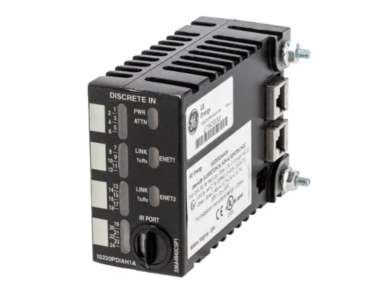
You must distinguish between a failure in the active processing unit and the passive termination unit. The I/O pack (often designated with an IS220 prefix) contains the microprocessors, analog-to-digital converters, and network interfaces. It is the active component responsible for digitizing field signals and transmitting them over the IONet. The terminal board (such as a TREG or TBCI) is primarily passive. It contains terminal blocks, fuses, surge suppressors, and sometimes passive filtering components. When a specific channel fails, the fault usually lies within the active I/O pack. However, a blown fuse, a degraded varistor, or a damaged copper trace on the terminal board can mimic an I/O pack failure perfectly. Replacing the active pack will not fix a damaged passive board. Field engineers must test the terminal board independently before condemning the I/O pack.
Redundancy Limitations
Control systems utilize Simplex, Dual, or Triple Modular Redundant (TMR) setups depending on the criticality of the process. Simplex systems have no redundancy. A single module failure causes an immediate loss of control for those specific I/O points, leading to a localized or full process trip. TMR setups use three identical controllers and redundant I/O packs connected to specialized TMR terminal boards. TMR masks individual module failures by voting on the data. If one pack provides erratic data, the software voting mechanism in the controller outvotes it using the data from the other two packs. While TMR prevents immediate shutdowns, it requires strict maintenance discipline. Leaving a failed module in a TMR system reduces that specific node to a dual-redundant state. A second failure on that node will then cause a cascading fault and trip the turbine. Operators cannot treat TMR as an excuse to delay maintenance.
Typical Reasons for Mark VIe Module Failures
Thermal Stress and Component Aging
Heat accelerates the degradation of electronic components faster than any other environmental factor. Electrolytic capacitors inside the power supply section of the I/O pack contain a liquid electrolyte that evaporates over a 10-15 year lifecycle. As the electrolyte dries out, the Equivalent Series Resistance (ESR) increases significantly. This causes voltage ripples within the internal 5V and 3.3V power circuits. When the ripple exceeds the tolerance of the microprocessor, the module reboots or locks up. Semiconductor junctions also suffer from thermal cycling. Constant expansion and contraction create micro-cracks in the BGA (Ball Grid Array) solder joints beneath the main processors. Inadequate cabinet cooling accelerates this aging process. HVAC failures in the control room or clogged cabinet fan filters directly reduce the lifespan of the hardware. Keeping cabinet temperatures below 35°C extends module life exponentially.
Power Supply Anomalies
The internal power distribution of the module is highly sensitive to external disturbances. Voltage spikes from grid fluctuations, heavy motor starts, or lightning strikes can bypass external surge suppressors and hit the terminal board. Ground faults in the field wiring can introduce high currents into the sensitive analog inputs, burning out the isolation barriers. Poor power quality, including harmonic distortion on the main 125VDC or 24VDC supply lines, stresses the internal DC-DC converters of the GE Mark VIe Control Module. Over time, these anomalies degrade the optical isolators and transformers within the pack. Once the isolation barrier fails, the module can no longer read field signals accurately and will likely generate persistent diagnostic alarms regarding reference voltages.
Environmental Contamination
Control cabinets operate in harsh industrial environments. Conductive dust from coal handling, cement manufacturing, or metal processing can bypass standard cabinet filters and settle on exposed circuit boards. High humidity causes condensation on these dust particles. When moisture mixes with conductive dust, it creates short circuits across component pins, leading to immediate hardware failure. Corrosive gases present an even more severe threat. Hydrogen sulfide (H2S) in refineries and wastewater plants attacks exposed copper traces and silver solder, creating non-conductive copper sulfide whiskers. Manufacturers apply conformal coating (usually acrylic or silicone) to protect the boards. However, thermal cycling and chemical exposure break down this coating over time, leaving the hardware vulnerable to atmospheric attack.
Firmware, IONet Communication Errors, and Network Storms
Not all failures involve broken physical hardware. Network packet loss can cause a module to drop offline intermittently. IONet switch degradation, such as a failing port or a dying switch power supply, leads to dropped frames and synchronization errors between the controller and the I/O pack. Corrupted flash memory within the I/O pack prevents it from booting properly after a power cycle. Network storms occur when excessive broadcast or multicast traffic floods the IONet. This overwhelms the processing capacity of the I/O pack's network interface, causing it to drop its connection. Cybersecurity anomalies, such as unauthorized network scanning or improper IGMP snooping configurations on the switches, can also mimic physical hardware failures by causing the module to lock up.
Fault Finding Framework
Utilizing ToolboxST for Alarm Triage
ToolboxST is the primary diagnostic software for the Mark VIe system. When a fault occurs, open the Alarm Viewer immediately. You must differentiate between a "Process Alarm" and a "Diagnostic Alarm." A Process Alarm indicates that a field instrument crossed a programmed threshold, such as high lube oil temperature. A Diagnostic Alarm indicates an internal fault within the control hardware itself. Navigate to the specific I/O pack in the Hardware tab. Double-click the module to open the Property Editor and view the Diagnostics tab. Review the specific hexadecimal fault codes. ToolboxST will specify if the error relates to a specific analog channel out of range, an internal power supply failure, or a loss of IONet communication. Do not guess; let the software point you to the exact subsystem.
Physical Inspection and LED Status Indicators
Physical inspection provides immediate clues on the plant floor. Every I/O pack features standard LED states that communicate its current health. Observe the Power, Run, Fail, and Status LEDs before connecting any laptops. Document the exact LED behavior before removing power from the cabinet.
Standard LED Diagnostic States
LED Indicator
State
Meaning / Required Action
Power (Green)
Solid
Internal 5V/3.3V power is good. No action needed.
Power (Green)
Off
No power from terminal board. Check fuses and incoming DC supply.
Run (Green)
Solid
Module is actively communicating and executing logic.
Fail (Red)
Solid
Severe hardware fault or boot failure. Replace module.
Status (Orange/Red)
Flashing
Firmware mismatch, unconfigured state, or loss of IONet. Check ToolboxST.
Eliminating External Variables
External wiring, power supply, and communication issues can resemble Mark VIe module failures. Before replacing hardware, technicians should verify supply voltage, fuse continuity, field wiring, IONet connections, and instrument signals. Systematic troubleshooting helps identify the actual fault, prevent unnecessary module replacement, and reduce downtime.
Root Cause Analysis (RCA) Documentation
Root Cause Analysis (RCA) helps identify recurring Mark VIe module failures and improve system reliability. Maintenance teams should record alarm logs, ToolboxST trend data, LED indicators, operating conditions, and module identification details. Complete documentation supports troubleshooting, maintenance planning, and future failure prevention.
Strategies to Replace Mark VIe Modules
Sourcing OEM New Modules
OEM Mark VIe modules provide manufacturer-backed quality assurance, warranty coverage, and verified hardware specifications. However, replacement availability and lead times may vary, particularly for legacy systems. Buyers should confirm part numbers, hardware revisions, firmware compatibility, and delivery schedules before ordering.
Certified Refurbished and Surplus Procurement
Refurbished and surplus Mark VIe modules can provide cost-effective replacement options for legacy control systems. Buyers should verify exact part numbers, hardware revisions, functional testing, ESD-safe handling, and warranty coverage. Suppliers offering documented IONet communication tests and quality management procedures can help reduce compatibility and reliability risks.
Component-Level Repair
Component-level repair involves sending the failed module to a specialized electronics laboratory. Technicians troubleshoot the board down to the microchip level, replacing degraded capacitors, damaged relays, and burnt copper traces. This is viable for non-critical systems or when dealing with highly obsolete parts that are unavailable on the surplus market. However, repair carries the risk of recurring failures. Fixing one burnt trace does not address the underlying thermal degradation of the remaining 15-year-old components on that same board. Repair turnaround times can also exceed the downtime limits of critical process applications, making it a poor choice for emergency recovery.
Comparison of Replacement Strategies
Strategy
Typical Lead Time
Reliability & Risk Profile
Best Application
OEM New
Long (Weeks/Months)
Highest reliability, full warranty, potential firmware upgrade required.
Planned upgrades, capital projects, stocking new facilities.
Certified Refurbished
Short (Days)
High reliability if vetted properly, matches existing hardware revisions.
Emergency breakdowns, legacy system maintenance, exact revision matching.
Component Repair
Moderate (Weeks)
Risk of secondary component failure, dependent on lab expertise.
Compare Replacement Choices: Cost, Risk and Long-Term Use
Lead Time vs. Downtime Costs
You must calculate the operational risk of maintaining on-site strategic spares. Compare the cost of holding inventory against the cost of lost production. If your facility loses massive revenue per hour during a turbine trip, waiting three days for a replacement part to ship is financially unacceptable. Relying on just-in-time procurement is too risky for critical control nodes. Identify the most vulnerable modules in your architecture—specifically the main controllers, IONet switches, and critical trip modules—and stock certified spares on-site in a climate-controlled environment.
Safety and Compliance (SIL Requirements)
Replacing modules in SIL-rated (Safety Integrity Level) systems requires strict regulatory compliance. Safety systems rely on certified hardware fault tolerance and specific failure rate data. You cannot replace a SIL-certified module with a standard process module, even if they look identical and have similar part numbers. The replacement part must carry the exact same safety certifications from agencies like exida or TÜV. Failure to maintain this compliance invalidates your safety case. It exposes the facility to severe regulatory fines and unacceptable operational risks. Always verify the SIL rating of the replacement hardware before installation.
Eliminating the Pain of Obsolescence and Migration Planning
Control systems move through predictable lifecycle phases: Active, Active-Mature, End of Life, and Obsolete. Navigating these phases requires proactive planning rather than reactive scrambling. A single module failure should trigger an audit of your entire control system's lifecycle status. If you struggle to find a replacement GE Mark VIe Control Module today, the problem will only worsen next year as global surplus inventory shrinks. Use this failure as a catalyst for long-term migration planning. Upgrading in planned phases prevents future procurement bottlenecks and eliminates the stress of sourcing obsolete parts during an emergency outage.
Conclusion
Audit your current inventory of critical spares and verify their physical condition and exact part numbers.
Download and archive your current system diagnostic logs and ToolboxST configuration files to a secure engineering workstation.
Consult with a certified control systems specialist to evaluate any hardware currently showing intermittent diagnostic alarms before it fails completely.
Implement a quarterly thermal imaging schedule for all control cabinets to detect early signs of component degradation.
FAQ
Q: Can a GE Mark VIe Control Module be hot-swapped while the turbine is running?
A: Yes, but only in Triple Modular Redundant (TMR) architectures. You must follow strict software and hardware isolation procedures. Hot-swapping a module in a Simplex architecture will instantly drop the control signals and trip the turbine. Simplex systems require a controlled shutdown.
Q: What does a solid red "FAIL" LED indicate on the I/O pack?
A: A solid red FAIL LED indicates a severe hardware failure or a boot sequence hang. It means the local microprocessor cannot execute its firmware. This usually requires a complete replacement of the I/O pack, as the internal logic has failed.
Q: How do I match the firmware on a replacement Mark VIe module?
A: You must use ToolboxST. After physically installing the module, bind its new MAC address to the hardware tree. ToolboxST will detect the mismatch and prompt you to download the baseline firmware and configuration parameters directly to the new pack.
Q: What is the typical lifespan of a GE Mark VIe Control Module?
A: Under optimal environmental conditions, these modules last 10 to 15 years. However, high cabinet temperatures, poor power quality, and corrosive environments can degrade electrolytic capacitors and conformal coatings, reducing the lifespan to under 7 years.
Q: How can I verify the authenticity and compatibility of a refurbished Mark VIe module?
A: Check the exact part number prefixes. An IS200 prefix is a bare board, while IS215 is a full assembly. Ensure the hardware revision matches your system. Only buy from vendors who provide live load testing reports and handle parts in strict ESD-safe environments.
Q: Is it better to repair or replace a failed Mark VIe module?
A: Replacement with a certified refurbished or new unit is better for critical systems to minimize downtime. Repair is cheaper but takes weeks and carries the risk of secondary component failures due to the overall age of the unreplaced parts on the board.
Q: How do I back up the configuration before replacing the module?
A: Open ToolboxST and connect to the main controller. Perform a full system upload to pull the active configuration. Save this file to a secure, backed-up engineering workstation. This ensures you have the exact baseline parameters ready to push to the new module.